|
|
|
10.3 TIMING DIAGRAMS
������������Timing diagrams can be valuable when designing ladder logic for processes that are only dependant on time. The timing diagram is drawn with clear start and stop times. Ladder logic is constructed with timers that are used to turn outputs on and off at appropriate times. The basic method is;
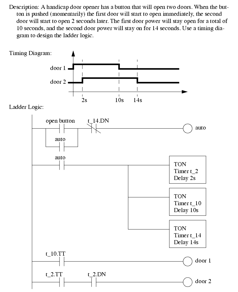
Consider the handicap door opener design in Figure 125 that begins with a verbal description. The verbal description is converted to a timing diagram, with t=0 being when the door open button is pushed. On the timing diagram the critical times are 2s, 10s, 14s. The ladder logic is constructed in a careful order. The first item is the latch to seal-in the open button, but shut off after the last door closes. auto is used to turn on the three timers for the critical times. The logic for opening the doors is then written to use the timers.

Search for More: |

Custom Search
|

|