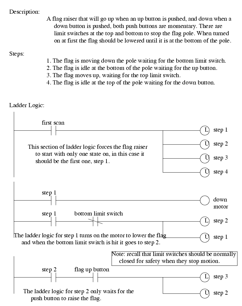
10.2 PROCESS SEQUENCE BITS
������������A typical machine will use a sequence of repetitive steps that can be clearly identified. Ladder logic can be written that follows this sequence. The steps for this design method are;
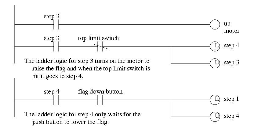
Consider the example of a flag raising controller in Figure 122 and Figure 123. The problem begins with a written description of the process. This is then turned into a set of numbered steps. Each of the numbered steps is then converted to ladder logic.
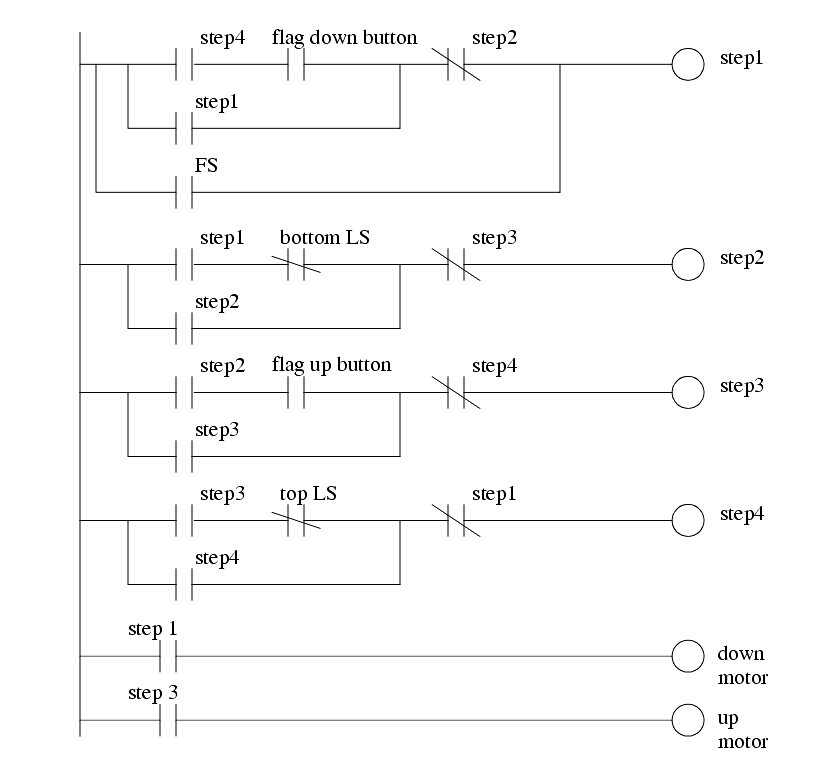
The previous method uses latched bits, but the use of latches is sometimes discouraged. A more common method of implementation, without latches, is shown in Figure 124.
Similar methods are explored in further detail in the book Cascading Logic (Kirckof, 2003).