6.3 Motor Models
������������
6.3.1 Basic Brushed DC Motors
������������
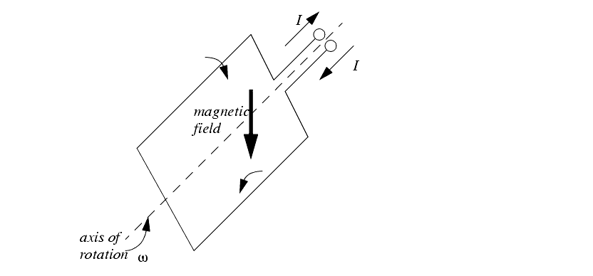
In a DC motor there is normally a set of coils on the rotor that turn inside a stator populated with permanent magnets. Figure 6.7 shows a simplified model of a motor. The magnetics provide a permanent magnetic field for the rotor to push against. When current is run through the wire loop it creates a magnetic field.
Figure 6.7 A Simplified Rotor
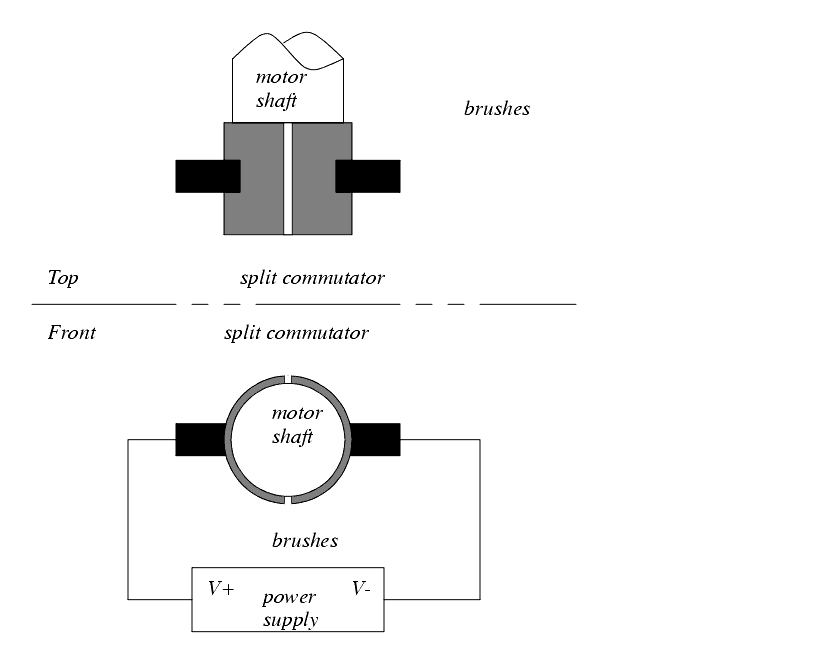
The power is delivered to the rotor using a commutator and brushes, as shown in Figure 6.8. In the figure the power is supplied to the rotor through graphite brushes rubbing against the commutator. The commutator is split so that every half revolution the polarity of the voltage on the rotor, and the induced magnetic field reverses to push against the permanent magnets.
Figure 6.8 A Split Ring Commutator
The direction of rotation will be determined by the polarity of the applied voltage, and the speed is proportional to the voltage. A feedback controller is used with these motors to provide motor positioning and velocity control.
These motors are losing popularity to brushless motors. The brushes are subject to wear, which increases maintenance costs. In addition, the use of brushes increases resistance, and lowers the motors efficiency.
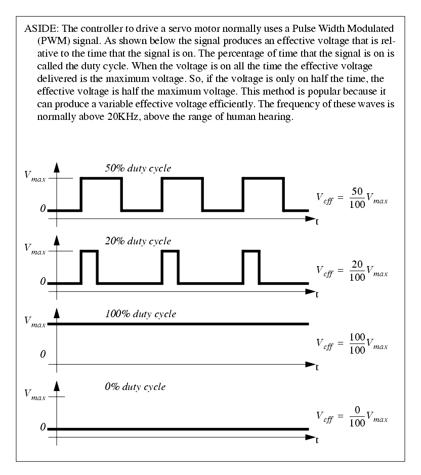
Figure 6.9 Pulse Width Modulation (PWM) For Control
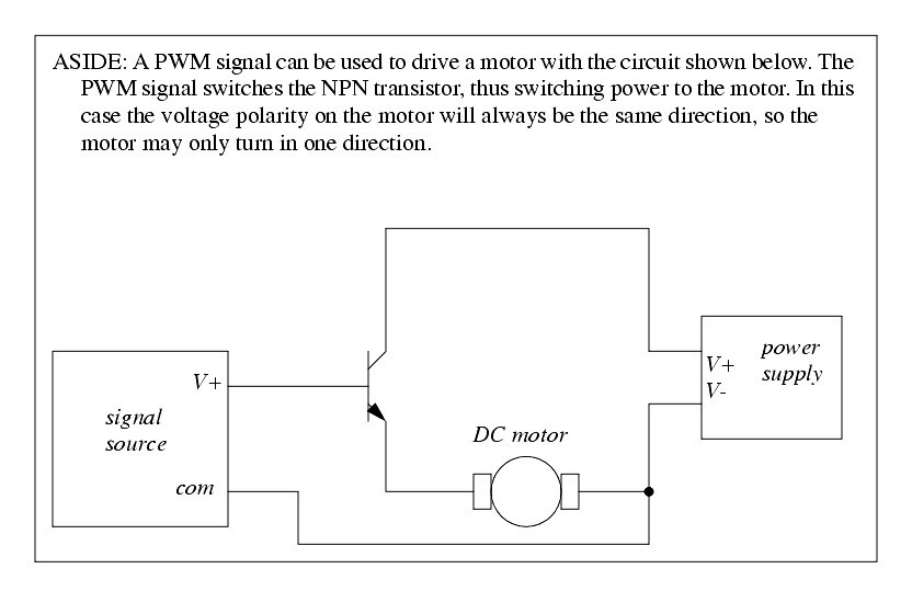
Figure 6.10 PWM Unidirectional Motor Control Circuit
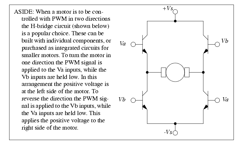
Figure 6.11 PWM Bidirectional Motor Control Circuit
Figure 6.12 Model of a permanent magnet DC motor
Figure 6.13 Torque speed curve for a permanent magnet DC motor
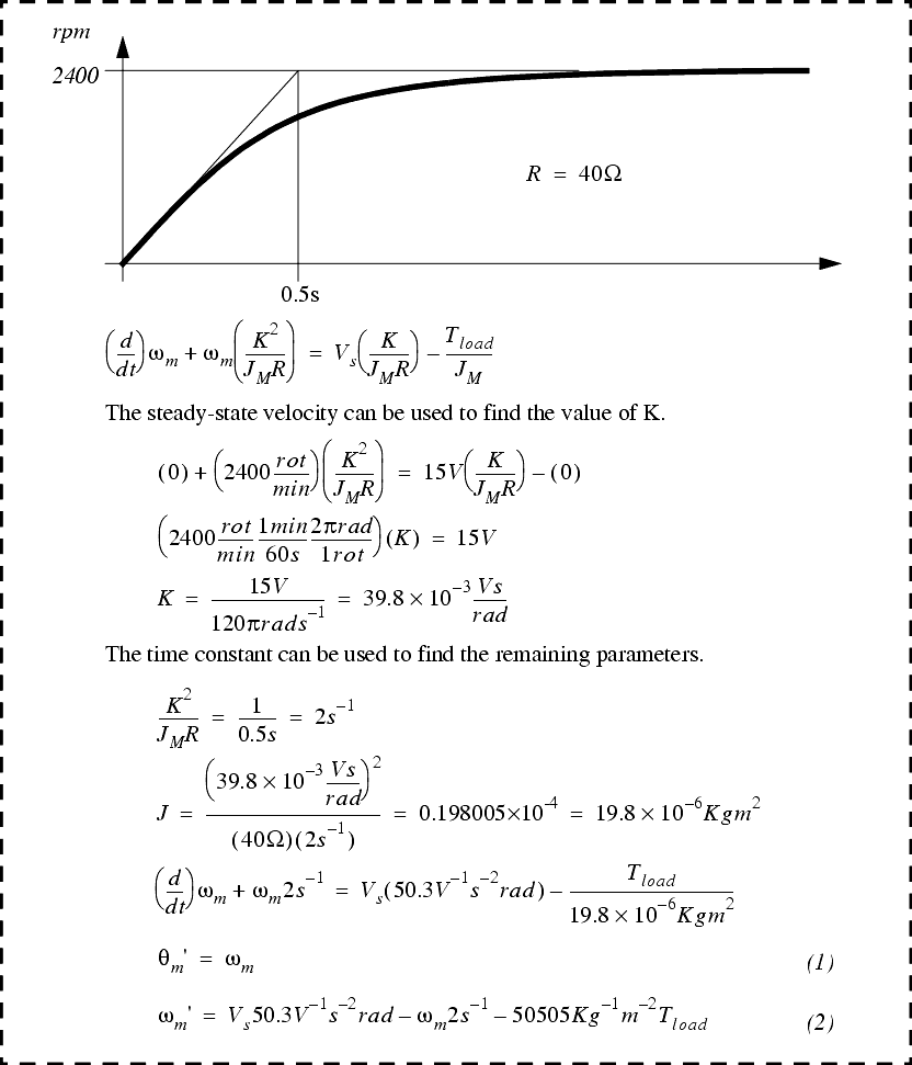
Figure 6.14 Motor speed curve and the derived differential equation

