|
|
jpf 1. Conversational Programming
Conversational programming is the process of using a graphical interface program on the CNC machine to plan and execute machining cycles. This form of programming has become quite popular in recent years. With conversational programming, the program is created at the CNC machine. Generally speaking, the conversational program is created using graphic and menu-driven functions. The programmer will be able to visually check whether various inputs are correct as the program is created. When finished, most conversational controls will even show the programmer a tool path plot of what will happen during the machining cycle.
Conversational controls vary substantially from one manufacturer to the next. In most cases, they can essentially be thought of as a single-purpose CAM system, and thus do provide a convenient means to generate part programs for a single machine. Be forewarned, though, that some of these controls, particularly older models, can only be programmed conversationally at the machine, which means you can't utilize other means such as off-line programming with a CAM system. However, most new models can operate either in a conversational mode or accept externally generated G-code programs.
 Taper Cycle
To select Turning operation press
 Type of Taper Turning
External  Taper Turning
 Internal Taper Turning
To modify the type of turning move onto this icon and press
We will only use external tapering.
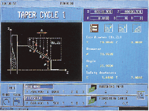

Figure 9
Whenever the type of taper is changed the CNC modifies the icon and displays the relevant geometrical help screen.

 Shape of the part before and after the tapered section
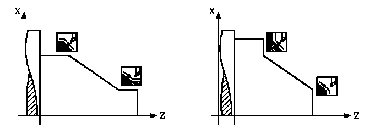 The icons and define the type of section before and after the tapered section.

To modify the type of section move over the relevant icon and press
Remember that the shape before and after the tapered section is assumed to be machine. The machine will generate tool paths and clearances based on the shape that is defined. Whenever one of these is changed the CNC modifies the icon and displays the relevant geometric help screen.
 Work quadrant
The icon defines the type of corner to be machined.


To modify the work quadrant move over the icon and press. The CNC will display the next icon available.
Coordinates of the starting point (Xi, Zi) and coordinates of the end point (Xf, Zf)
 These cooridants are defined in the same manner as described above. Move over to the value using the arrow keys, enter the appropriate values and press
Final Diameter (φ )
 The final diameter is the diameter at the small end of the taper. The machine will use the angle, and the start point (Xi, Yi) and the diameter to define the tool path. This diameter may have to be calculated. To enter a diameter value move onto this data item, type in the value required and press
Angle ( α)
 This is the angle from the Z-axis, taken from the (Xi,Yi) point defined above. This value is always positive. To enter the angle move onto this data item, type in the value required and press
Safety Distance
In order to avoid collisions with the part, the CNC allows a point for approach to the part to be defined. The Safety Distance indicates the position of the approach point with respect to the theoretical corner.

 To modify one of these values move onto the relevant data item, type in the required value and press key.

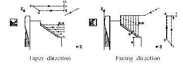
Machining direction
 To select the machining direction (taper direction or facing direction) move onto the icon for the data zone for roughing and finishing and press key
The icon changes and the help graphic are updated.
 Rounding Cycle
To select Rounding operation press
 Type of Rounding
External Rounding
 Internal Rounding
To modify the type of rounding move onto this icon and press
Whenever the type of rounding is changed the CNC modifies the icon and displays the relevant geometrical help screen.

 Concave and convex rounding
 The icons and define the type of rounding required to be done.
To modify the type of rounding move onto the relevant icon and press
Whenever any of these is changed the CNC modifies the icon and displays the relevant geometrical help screen.

 Shape of the part before and after the rounding section
The icons and define the type of section before and after the rounding section.
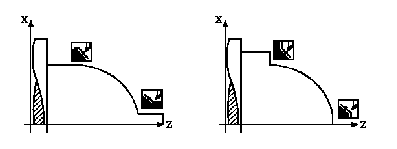

To modify the type of section move onto the relevant icon and press
Whenever any of these is changed the CNC modifies the icon and displays the relevant geometrical help screen. Keep in mind that like the tapering cycle the machine assumes that the geometry before and after the rounding section is already formed. It will use this to define clearances for the tool.
 Work quadrant
The icon defines the type of corner required to be machined.

 To modify the work quadrant move over the icon and press. The CNC will display the next icon available.
Coordinates of the starting point (Xi, Zi) and coordinates of the end point (Xf, Zf)
 These cooridants are defined in the same manner as described above. Move over to the value using the arrow keys, enter the appropriate values and press
Rounding radius (R)
 This radius is the actual radius of the curve, not the diameter. The machine finds the start and end points of the radius based on the (X,Z) value entered above. To change the radius move over this data item, type in the value required and press
Safety Distance
In order to prevent collisions with the part, the CNC allows an approach point for the part to be established. The safety distance indicates the position of the approach point with respect to the theoretical corner.

 To modify one of these values move over the corresponding data item, type in the required value and press.
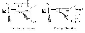
Machining direction
 To select the machining direction (turning direction or facing direction), move onto the icon for the zone for Roughing and Finishing data and press
The icon changes and the help graphic are updated. Whether the turning of facing direction is used depends on the type of tool that is being used.
 Grooving Cycle
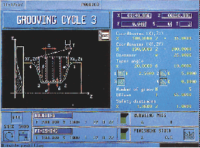 To select grooving operation press

 Types of Grooving
External  Grooving
 Internal Grooving
To modify the type of grooving move onto this icon and press
Coordinates of the starting point (Xi, Zi) and coordinates of the end point (Xf, Zf)
 These cooridants are defined in the same manner as described above. Move over to the value using the arrow keys, enter the appropriate values and press
Final diameter (φ ) and coordinate of the bottom of the groove (R)
 Depending on the type of grooving selected one of these two data items must be defined. To do this, move on to this data item, key in the required value and press
Inclination angles ( α, β )
This data must be defined for grooving with incline walls


To do that, position over the data, key in the desired value and press
The next example shows grooves with α=20° and β=0°

Type of machining to be carried out on each corner.
This data must be defined for grooving with incline walls.
 The type of machining must be defined for all four corners of the groove.
To change the type of machining, position over this icon and press
For the rounded corner (radius blend), the rounding radius (R) must be defined and, for the chamfer, the distance from the theoretical corner to the chamfer point (C).
Dwell at the bottom (t)
 Define the waiting time in seconds, after each deepening, until the withdrawal movement starts. To define this, move on to the data item, key in the required value and press
Safety distance
In order to prevent collisions with the part, the CNC allows a point of approach to the part to be defined. The safety distance indicates the position of the approach point with respect to the initial corner.
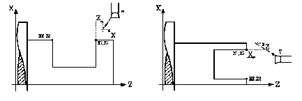

To modify these values move over the relevant data, key in the required value and press
 Types of machining for the finishing pass
This data must be defined for grooving with incline walls.
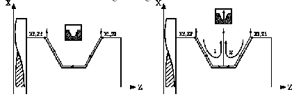
 To change the type of machining, position over the icon and press
 Threading Cycle
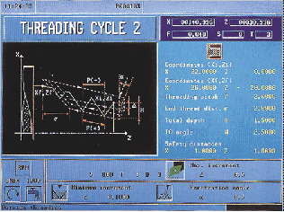 To select Threading operation press

 Types of Threading
External  Threading
 Internal Threading
To modify the type of rounding move onto this icon and press
Whenever one changes the type of threading the CNC modifies the icon and displays the relevant geometrical help screen. Internal threading is only used with very large holes, larger than 1inch diameter. For smaller internal threads use the tapping cycle described later.
Coordinates of the starting point (Xi, Zi) and coordinates of the end point (Xf, Zf)
 These cooridants are defined in the same manner as described above. The (Xi,Zi) is the location of the start of the thread. Keep in mind that this cycle assumes that the part has already been turned down to the largest diameter of the screw. For standard threads this is a flat surface equal to the major diameter of the thread. For pipe threads this is a tapered surface. Move over to the value using the arrow keys, enter the appropriate values and press
Thread Pitch (P)
The thread pitch may be set along the taper of the thread or along its associated axis.
In either case, parameter P" must be used, but with different signs:
«P» with positive sign. When programming the pitch along the taper of the thread.
«P» with negative sign. When programming the pitch along the associated axis.
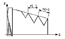

To set the pitch, move over this data item, key in the value required and press
Distance to end of Thread (σ )
 Indicates at what distance from the end of the thread the thread starts to be reduced. For all thread this distance must be a positive number. When the tool gets to the location of Xf+σ the tool will begin to withdraw from the work piece. By the time the tool reaches the end of the thread it is fully withdrawn from the work piece. In this withdrawal movement threading is continued.
Move on to this data item, key in the required value and press
Safety distance
 In order to prevent collisions with the part, the CNC allows an approach point to the part to be established. The safety distance indicates the position of the approach point with respect to the theoretical corner.
The value of the safety distance on X is always defined in radii.
 To modify one of these values, move over the corresponding data item, key in the required value and press
 Drilling Cycle
To select the Drilling cycle and the Tapping cycle press


 Machining on the face or side of the part:
Machining on the face of the part
All drilling operations must be performed on the face of the part; the lathe does not contain the attachment to drill on the side of the part.
Coordinates of the starting point (X, Z)
 The coordinates are defined one by one. The Z value will be the end of the part, and the x value will always be zero, i.e. drilling on the turning center of the work piece. The lathe does not contain the attachment to do off center drilling. Manually enter the value for Z, and 0 for X and press
Total depth (L)
 This is the depth that you would like to drill to. Remember that this depth cannot exceed the length of the drill bit protruding from the head. Measure the length of the drill before any drilling cycle. To change this data item, key in the required value and press
Dwell at the bottom (t)
Define the waiting time in seconds, after each deepening, until the withdrawal movement starts. To define this, move onto this data item, key in the required value and press
Tapping Cycle
 All the parameters are defined in the same way as that of drilling cycle.

 Profiling cycle
To select Positioning operation press
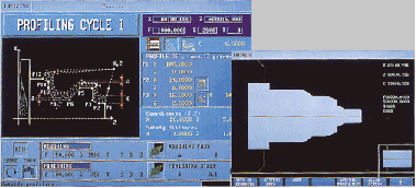

PROFILE DEFINITION
This mode allows the profile to be defined by means of the description of its theoretical corners.
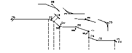 Up to 12 points can be used for defining said corners. Point P1 is the profile starting point. The remaining points must be correlative.

 Keys should be used for selecting and leaving the window containing the profile definition points and keys for defining said points.
 The coordinates are defined one by one. After moving onto the coordinates of the axis to be defined, one can:
a) Manually enter the value. Key in the value required and press
At all the intermediate points of the profile the type of machining required to be done on the corner must be defined.


To modify the type of machining move onto this icon and press
In the case of the rounded corner the rounding radius (R) has to be defined and in the case of the chamfer the distance from the theoretical corner up to the point where the chamfer is to be made (C).
When the 12 definition points are not used the following conditions have to be complied with:
* The CNC does not take into account the type of machining of the last profile point.
* The first point not used must be defined with the same coordinates as the last point of the profile. In the example shown in the figure above P10 = P9 must be defined.
Machine Settings - Production Phase
Step 1 Turn On Machine

 Turn on machine by pulling up red lever on the back of machine.

 Press ‘ SHIFT ‘Esc’
 Press again ‘ SHIFT ‘Esc’
Press ‘ RESET’ , this action will turn on oil pump and you will see message ‘ 11 lubricating ways’
Press ‘MAIN MENU’
Press again ‘MAIN MENU’
Now you can open gate to set home position of the machine.
Step 3 Load the Part
Turn the headstock until the square adjustment nut is facing up. Insert the wrench and open the jaws until the stock can be inserted. Insert the stock to be turned and tighten the jaws until they are snug on the part. Be sure that you have an extra ½ inch of material beyond what you would like to machine sticking out of the stock. This is to ensure that you do not accidentally machine the headstock.
 Check for Concentricity
Press “S” “50” to set the spindle speed to 50RPM and press cycle start
Then press the “spindle on counter clockwise” button to set the spindle in motion.
Look carefully at the end of the stock. If it is wobbling it means that the stock is not mounted on center in the headstock. If this is the case, stop the spindle, loosen the headstock, reposition the part and recheck for concentricity.
Step 4 Tool Calibration
Much like the CNC mill the lathe needs to have tools size and offset values defined before using them. This is done by defining tool geometry and touching off the tool on the actual part. This equivalent to setting the tool offset value using the dead tool.
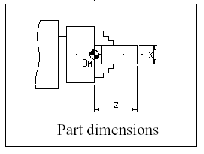
1. - Measure the part diameter accurately, to within +/- .001 inches.
- Go to the tool calibration window. Press ‘F1’
- Enter the X value, the value of the diameter.
- Enter the Z value, the length that you would like to machine.

2- Start the spindle.
 3- Select the tool to be calibrated.
 , Tool number, 8
4- Jog the axes slowly until touching the part along the X-axis. Press:
 The CNC shows the tool length along the X-axis.
5- Jog the axes slowly until touching the part along the Z-axis. Press:
The CNC shows the tool length along the Z-axis.
6- Enter the rest of the data (angle, width, radius and location code). For tools that are already loaded these values will already be set, do not change them.
I, K values are set to zero when calibrating.
To calibrate another tool, repeat steps 3, 4, 5 and 6.
Now you can define conversational manufacturing operations.
Step 5 Define Manufacturing Parameters

 Now that you have completed your drawing sets for the different processes that you would like to perform it is time to enter the data for the process. Select the appropriate cycle as defined above and enter in the relevant data. Usually you will start with a turning cycle so that is the one that will be explained here. Look at the example shown in the planning phase for more details. The turning cycle is selected by pressing
Under the tool menu we enter T8 for the tool and press This will rotate tool 8 into the cutting position. The values for (Xi,Zi) and (Xf,Zf) and (d) are entered into the parameter spaces, pressing enter after each one. The safety distances are left at 0.50 and 0.50. On the bottom of the screen is the area that we enter the speeds and feeds into. The first thing that is selected is the CSS icon. This stands for Constant Surface Speed. This means that the CNC will automatically adjust the speed of the piece to maintain a constant speed between the surface of the part and the tool. This same tool bar also contains the coolant control, which is always on, the range, which should always stay at 1, and the direction, which should always be clockwise. Next there are two screens, one labeled Roughing and one labeled Finishing. In the roughing screen we define the speed, feed, tool, and depth of cut. These values are found in the Valenite tool manuals and are specific to a type of insert tool and material. Typically these will be left alone, unless you are cutting something other than aluminum. If you are cutting steel you will need to change the inserts in the tool, change speed and feed values, and verify them in the Valenite tool manuals. The machine will take as many passes as needed with the roughing values until it gets to the depth of the final diameter. Then it will switch cutting parameters to those specified in the finishing menu, and make one last finish cut. This is the most important cut because it will dictate the surface finish and the accuracy of the final part.
Step 6 Simulate the Cycle
 Once all of the correct parameters are entered the cycle can be simulated. While in the cycle screen press the button labeled “Graphics”. This will create a blank screen with a few options on the side. Select “X-Z Solid” and enter in the size of the part. For the example we have been using it is Z=4, and X=3. This will create a picture of a round part that is 4 inches long and 3 inches in diameter. To simulate the program turn the feed rate to zero and press
If there is no movement of the machine turn the feed up and watch the graphic. The machine will show the tool move into the part, and make the cut. When complete the graphic will show the final result. If this is incorrect, or something does not look right, press escape to get back to the cycle definition. Look over the values and make sure every thing is correct. Then reenter the graphics menu and rerun the simulation. Before continuing show the professor the successful graphic screen.
Step 7 Run the Cycle
SHOW THE SUCCESSFUL SIMULATION GRAPHIC TO YOUR PROFESSOR BEFORE RUNNING THE PROGRAM.
 To run the program press escape to get back to the cycle definition page. Press escape again and a green cycle button will appear in the upper right corner of the screen. Turn the speed to 100% and the feed to 0%. Press
This will start the machining process. If anything goes wrong press the red cycle stop button, or the E-stop immediately. Slowly turn the feed up and watch the tool move into the part. Watch the first pass to make sure that the tool will not hit the headstock and that things are going correctly. If all is well turn the speed up to 100% and watch keep an eye on the machine. Do not leave the machine while a cycle is running. After the cycle is complete open the doors and check the part. If the part is the correct size, repeat steps 5 through 7 for the next process. If a different tool is needed, repeat step 4 to calibrate the tool. Remember that this is a very expensive piece of lab equipment so if you are unsure of what you are doing ASK SOMEONE WHO KNOWS.
|
|
 Taper Cycle
 Type of Taper Turning
  Taper Turning
  Internal Taper Turning


 Shape of the part before and after the tapered section
 The icons and define the type of section before and after the tapered section.
 Work quadrant

 These cooridants are defined in the same manner as described above. Move over to the value using the arrow keys, enter the appropriate values and press
 The final diameter is the diameter at the small end of the taper. The machine will use the angle, and the start point (Xi, Yi) and the diameter to define the tool path. This diameter may have to be calculated. To enter a diameter value move onto this data item, type in the value required and press
 This is the angle from the Z-axis, taken from the (Xi,Yi) point defined above. This value is always positive. To enter the angle move onto this data item, type in the value required and press
 To modify one of these values move onto the relevant data item, type in the required value and press key.
 To select the machining direction (taper direction or facing direction) move onto the icon for the data zone for roughing and finishing and press key
 Rounding Cycle
 Type of Rounding
  Rounding
  Internal Rounding
 Concave and convex rounding
 The icons and define the type of rounding required to be done.
 Shape of the part before and after the rounding section

 Work quadrant
 To modify the work quadrant move over the icon and press. The CNC will display the next icon available.
 These cooridants are defined in the same manner as described above. Move over to the value using the arrow keys, enter the appropriate values and press
 This radius is the actual radius of the curve, not the diameter. The machine finds the start and end points of the radius based on the (X,Z) value entered above. To change the radius move over this data item, type in the value required and press
 To modify one of these values move over the corresponding data item, type in the required value and press.
 To select the machining direction (turning direction or facing direction), move onto the icon for the zone for Roughing and Finishing data and press
 Grooving Cycle
 To select grooving operation press
 Types of Grooving
  Grooving
 Internal Grooving
  These cooridants are defined in the same manner as described above. Move over to the value using the arrow keys, enter the appropriate values and press
 Depending on the type of grooving selected one of these two data items must be defined. To do this, move on to this data item, key in the required value and press


 The type of machining must be defined for all four corners of the groove.
 Define the waiting time in seconds, after each deepening, until the withdrawal movement starts. To define this, move on to the data item, key in the required value and press

 Types of machining for the finishing pass
 To change the type of machining, position over the icon and press
  Threading Cycle
 To select Threading operation press
 Types of Threading
  Threading
  Internal Threading
  These cooridants are defined in the same manner as described above. The (Xi,Zi) is the location of the start of the thread. Keep in mind that this cycle assumes that the part has already been turned down to the largest diameter of the screw. For standard threads this is a flat surface equal to the major diameter of the thread. For pipe threads this is a tapered surface. Move over to the value using the arrow keys, enter the appropriate values and press

 Indicates at what distance from the end of the thread the thread starts to be reduced. For all thread this distance must be a positive number. When the tool gets to the location of Xf+σ the tool will begin to withdraw from the work piece. By the time the tool reaches the end of the thread it is fully withdrawn from the work piece. In this withdrawal movement threading is continued.
 In order to prevent collisions with the part, the CNC allows an approach point to the part to be established. The safety distance indicates the position of the approach point with respect to the theoretical corner.
 To modify one of these values, move over the corresponding data item, key in the required value and press
 Drilling Cycle

 Machining on the face or side of the part:
 The coordinates are defined one by one. The Z value will be the end of the part, and the x value will always be zero, i.e. drilling on the turning center of the work piece. The lathe does not contain the attachment to do off center drilling. Manually enter the value for Z, and 0 for X and press
 This is the depth that you would like to drill to. Remember that this depth cannot exceed the length of the drill bit protruding from the head. Measure the length of the drill before any drilling cycle. To change this data item, key in the required value and press
 All the parameters are defined in the same way as that of drilling cycle.
 Profiling cycle

 Up to 12 points can be used for defining said corners. Point P1 is the profile starting point. The remaining points must be correlative.
 Keys should be used for selecting and leaving the window containing the profile definition points and keys for defining said points.
 The coordinates are defined one by one. After moving onto the coordinates of the axis to be defined, one can:


 Turn on machine by pulling up red lever on the back of machine.
 Press ‘ SHIFT ‘Esc’
  Press again ‘ SHIFT ‘Esc’

 CNC1540 is equipped with the capability to set home position anywhere on X-axis or Z-axis. But it’s really important to know what are the soft limits of the machine. When the machine is first turned on check the home position by moving the headstock until the X-axis and Z-axis home variables read zero. This should be a point to the front side of the mill and about 1.5 inches from the headstock. One can set home position by following way

 Press ‘X’ , ZERO , CYCLE START ,this action will make current position ‘home position’ along X- axis. Recommended method to set home position along X- axis is align indicators on Turret base and cross slide and then press ‘X’ , ZERO , CYCLE START

 Press ‘Z’ , ZERO , CYCLE START , this action will make current position ‘home position’ along Z- axis. It is recommended to move turret to soft limits to make sure that turret is not colliding with spindle, spindle jaws or tail stock.
 Check for Concentricity

 3- Select the tool to be calibrated.
 , Tool number, 8
 The CNC shows the tool length along the X-axis.
 Now that you have completed your drawing sets for the different processes that you would like to perform it is time to enter the data for the process. Select the appropriate cycle as defined above and enter in the relevant data. Usually you will start with a turning cycle so that is the one that will be explained here. Look at the example shown in the planning phase for more details. The turning cycle is selected by pressing
  Once all of the correct parameters are entered the cycle can be simulated. While in the cycle screen press the button labeled “Graphics”. This will create a blank screen with a few options on the side. Select “X-Z Solid” and enter in the size of the part. For the example we have been using it is Z=4, and X=3. This will create a picture of a round part that is 4 inches long and 3 inches in diameter. To simulate the program turn the feed rate to zero and press
  To run the program press escape to get back to the cycle definition page. Press escape again and a green cycle button will appear in the upper right corner of the screen. Turn the speed to 100% and the feed to 0%. Press