2.3.1 Theory
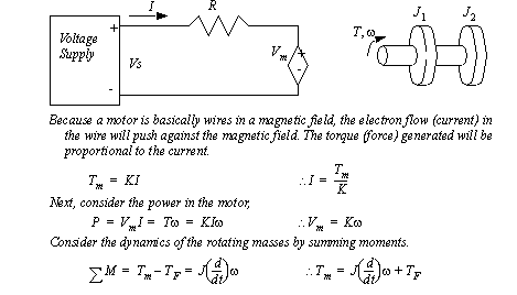
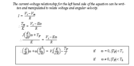
The differential equation is derived in Figure 2 The torque and inertia in a basic motor model and Figure 3 The first-order model of a motor experiencing kinetic friction to include a term for friction. In the derivation it is assumed that the motor is turning, and the friction is dynamic. Clearly the motor will not turn if the motor torque is less than the static friction limit.

The coefficients for the differential equation in Figure 3 The first-order model of a motor experiencing kinetic friction can be found for the motor in a dynamic case using steady state velocities. The static torque value can be found using the deadband limits.

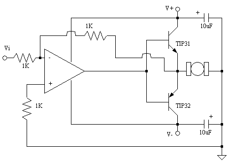
Eventually we will use the motors to control systems. In a simple form the motor can be turned on or off with transistors or relays. However we will want to vary the motor speed continuously over the range of operation. To do this we need a power amplifier that will work over a large range, as shown below. In this circuit the two transistors will drive the motor so that the voltage to the motor matches the input voltage. To do this the TIP 31 transistor will will be on when the voltage to the motor is positive, and current will flow left to right. When the TIP 32 transistor is on the voltage to the motor is negative and the current flows right to left. The transistors are controlled by the op-amp. The op-amp is set up as an inverting amplifier with a gain of -1, but it will provide a current amplification. If it was not present and the transistors drew too much current the input voltage would drop.

