|
|
|
|
|
|
|
|
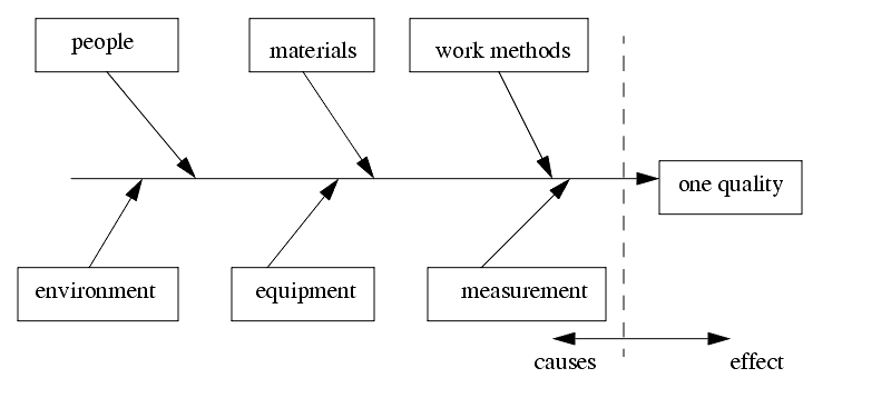
6.1 CAUSE AND EFFECT DIAGRAMS
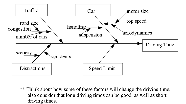
������������Consider a production team about to launch a new product. They must anticipate factors that will affect the final product
The cause and effect diagram was developed by Kaoru Ishikawa in 1943.
In quality we use these to find factors that have some role in a good/bad quality.
For manufacturing there are some more standard causes to consider.
How can a CE diagram be made up?
Brainstorming is a two stage process
Step 1: As a group, have each team member contribute ideas. If an idea is not good it doesn't matter. Add ideas to the diagram. Exhaust all ideas! NO CRITICISM!!!
Step 2: Review the diagram critically as a group. Voting will help to narrow down what are the most important factors.
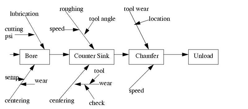
6.1.1 Process Diagrams
������������Another type of CE diagram is the Process-Analysis diagram. This is used when there are a number of operations or factors involved.
When considering CAUSES, there are two main types, assignable and chance.
Search for More: |

Custom Search
|
|