|
|
|
|
|
|
|
|
2.1 INTRODUCTION
������������Control engineering has evolved over time. In the past humans were the main method for controlling a system. More recently electricity has been used for control and early electrical control was based on relays. These relays allow power to be switched on and off without a mechanical switch. It is common to use relays to make simple logical control decisions. The development of low cost computer has brought the most recent revolution, the Programmable Logic Controller (PLC). The advent of the PLC began in the 1970s, and has become the most common choice for manufacturing controls.
PLCs have been gaining popularity on the factory floor and will probably remain predominant for some time to come. Most of this is because of the advantages they offer.
2.1.1 Ladder Logic
������������Ladder logic is the main programming method used for PLCs. As mentioned before, ladder logic has been developed to mimic relay logic. The decision to use the relay logic diagrams was a strategic one. By selecting ladder logic as the main programming method, the amount of retraining needed for engineers and tradespeople was greatly reduced.
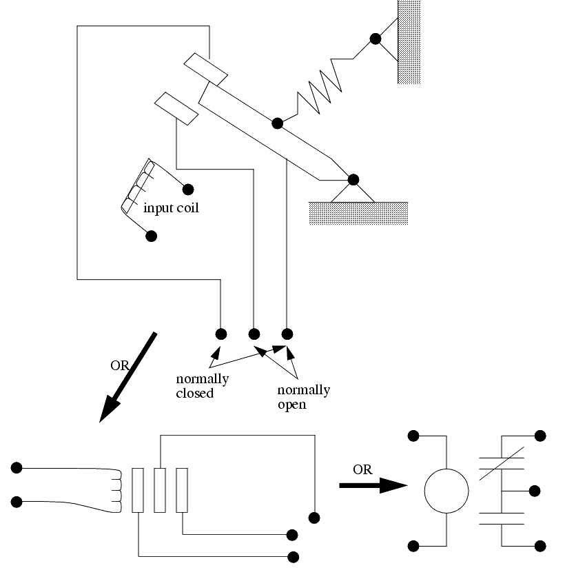
Modern control systems still include relays, but these are rarely used for logic. A relay is a simple device that uses a magnetic field to control a switch, as pictured in Figure 2. When a voltage is applied to the input coil, the resulting current creates a magnetic field. The magnetic field pulls a metal switch (or reed) towards it and the contacts touch, closing the switch. The contact that closes when the coil is energized is called normally open. The normally closed contacts touch when the input coil is not energized. Relays are normally drawn in schematic form using a circle to represent the input coil. The output contacts are shown with two parallel lines. Normally open contacts are shown as two lines, and will be open (non-conducting) when the input is not energized. Normally closed contacts are shown with two lines with a diagonal line through them. When the input coil is not energized the normally closed contacts will be closed (conducting).
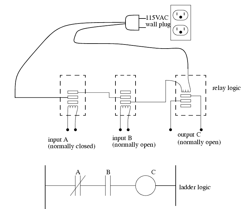
Relays are used to let one power source close a switch for another (often high current) power source, while keeping them isolated. An example of a relay in a simple control application is shown in Figure 3. In this system the first relay on the left is used as normally closed, and will allow current to flow until a voltage is applied to the input A. The second relay is normally open and will not allow current to flow until a voltage is applied to the input B. If current is flowing through the first two relays then current will flow through the coil in the third relay, and close the switch for output C. This circuit would normally be drawn in the ladder logic form. This can be read logically as C will be on if A is off and B is on.
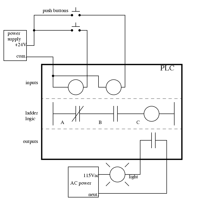
The example in Figure 3 does not show the entire control system, but only the logic. When we consider a PLC there are inputs, outputs, and the logic. Figure 4 shows a more complete representation of the PLC. Here there are two inputs from push buttons. We can imagine the inputs as activating 24V DC relay coils in the PLC. This in turn drives an output relay that switches 115V AC, that will turn on a light. Note, in actual PLCs inputs are never relays, but outputs are often relays. The ladder logic in the PLC is actually a computer program that the user can enter and change. Notice that both of the input push buttons are normally open, but the ladder logic inside the PLC has one normally open contact, and one normally closed contact. Do not think that the ladder logic in the PLC needs to match the inputs or outputs. Many beginners will get caught trying to make the ladder logic match the input types.
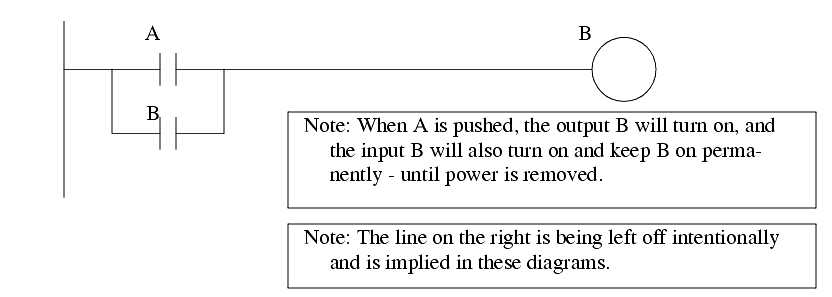
Many relays also have multiple outputs (throws) and this allows an output relay to also be an input simultaneously. The circuit shown in Figure 5 is an example of this, it is called a seal in circuit. In this circuit the current can flow through either branch of the circuit, through the contacts labelled A or B. The input B will only be on when the output B is on. If B is off, and A is energized, then B will turn on. If B turns on then the input B will turn on, and keep output B on even if input A goes off. After B is turned on the output B will not turn off.
2.1.2 Programming
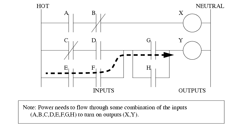
������������The first PLCs were programmed with a technique that was based on relay logic wiring schematics. This eliminated the need to teach the electricians, technicians and engineers how to program a computer - but, this method has stuck and it is the most common technique for programming PLCs today. An example of ladder logic can be seen in Figure 6. To interpret this diagram imagine that the power is on the vertical line on the left hand side, we call this the hot rail. On the right hand side is the neutral rail. In the figure there are two rungs, and on each rung there are combinations of inputs (two vertical lines) and outputs (circles). If the inputs are opened or closed in the right combination the power can flow from the hot rail, through the inputs, to power the outputs, and finally to the neutral rail. An input can come from a sensor, switch, or any other type of sensor. An output will be some device outside the PLC that is switched on or off, such as lights or motors. In the top rung the contacts are normally open and normally closed. Which means if input A is on and input B is off, then power will flow through the output and activate it. Any other combination of input values will result in the output X being off.
The second rung of Figure 6 is more complex, there are actually multiple combinations of inputs that will result in the output Y turning on. On the left most part of the rung, power could flow through the top if C is off and D is on. Power could also (and simultaneously) flow through the bottom if both E and F are true. This would get power half way across the rung, and then if G or H is true the power will be delivered to output Y. In later chapters we will examine how to interpret and construct these diagrams.
There are other methods for programming PLCs. One of the earliest techniques involved mnemonic instructions. These instructions can be derived directly from the ladder logic diagrams and entered into the PLC through a simple programming terminal. An example of mnemonics is shown in Figure 7. In this example the instructions are read one line at a time from top to bottom. The first line 00000 has the instruction LDN (input load and not) for input A. This will examine the input to the PLC and if it is off it will remember a 1 (or true), if it is on it will remember a 0 (or false). The next line uses an LD (input load) statement to look at the input. If the input is off it remembers a 0, if the input is on it remembers a 1 (note: this is the reverse of the LDN). The AND statement recalls the last two numbers remembered and if the are both true the result is a 1, otherwise the result is a 0. This result now replaces the two numbers that were recalled, and there is only one number remembered. The process is repeated for lines 00003 and 00004, but when these are done there are now three numbers remembered. The oldest number is from the AND, the newer numbers are from the two LD instructions. The AND in line 00005 combines the results from the last LD instructions and now there are two numbers remembered. The OR instruction takes the two numbers now remaining and if either one is a 1 the result is a 1, otherwise the result is a 0. This result replaces the two numbers, and there is now a single number there. The last instruction is the ST (store output) that will look at the last value stored and if it is 1, the output will be turned on, if it is 0 the output will be turned off.
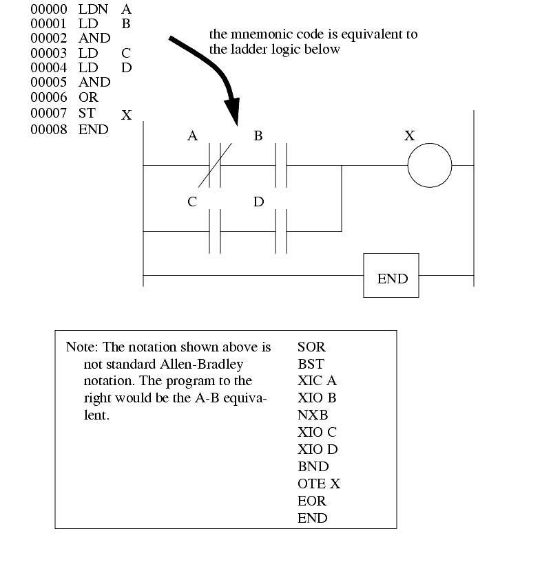
The ladder logic program in Figure 7, is equivalent to the mnemonic program. Even if you have programmed a PLC with ladder logic, it will be converted to mnemonic form before being used by the PLC. In the past mnemonic programming was the most common, but now it is uncommon for users to even see mnemonic programs.
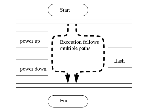
Sequential Function Charts (SFCs) have been developed to accommodate the programming of more advanced systems. These are similar to flowcharts, but much more powerful. The example seen in Figure 8 is doing two different things. To read the chart, start at the top where is says start. Below this there is the double horizontal line that says follow both paths. As a result the PLC will start to follow the branch on the left and right hand sides separately and simultaneously. On the left there are two functions the first one is the power up function. This function will run until it decides it is done, and the power down function will come after. On the right hand side is the flash function, this will run until it is done. These functions look unexplained, but each function, such as power up will be a small ladder logic program. This method is much different from flowcharts because it does not have to follow a single path through the flowchart.
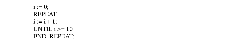
Structured Text programming has been developed as a more modern programming language. It is quite similar to languages such as BASIC. A simple example is shown in Figure 9. This example uses a PLC memory location i. This memory location is for an integer, as will be explained later in the book. The first line of the program sets the value to 0. The next line begins a loop, and will be where the loop returns to. The next line recalls the value in location i, adds 1 to it and returns it to the same location. The next line checks to see if the loop should quit. If i is greater than or equal to 10, then the loop will quit, otherwise the computer will go back up to the REPEAT statement continue from there. Each time the program goes through this loop i will increase by 1 until the value reaches 10.
2.1.3 PLC Connections
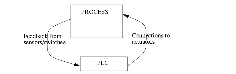
������������When a process is controlled by a PLC it uses inputs from sensors to make decisions and update outputs to drive actuators, as shown in Figure 10. The process is a real process that will change over time. Actuators will drive the system to new states (or modes of operation). This means that the controller is limited by the sensors available, if an input is not available, the controller will have no way to detect a condition.
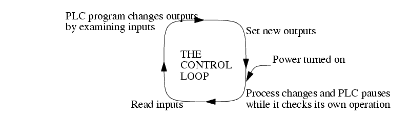
The control loop is a continuous cycle of the PLC reading inputs, solving the ladder logic, and then changing the outputs. Like any computer this does not happen instantly. Figure 11 shows the basic operation cycle of a PLC. When power is turned on initially the PLC does a quick sanity check to ensure that the hardware is working properly. If there is a problem the PLC will halt and indicate there is an error. For example, if the PLC power is dropping and about to go off this will result in one type of fault. If the PLC passes the sanity check it will then scan (read) all the inputs. After the inputs values are stored in memory the ladder logic will be scanned (solved) using the stored values - not the current values. This is done to prevent logic problems when inputs change during the ladder logic scan. When the ladder logic scan is complete the outputs will be scanned (the output values will be changed). After this the system goes back to do a sanity check, and the loop continues indefinitely. Unlike normal computers, the entire program will be run every scan. Typical times for each of the stages is in the order of milliseconds.
2.1.4 Ladder Logic Inputs
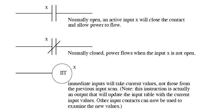
������������PLC inputs are easily represented in ladder logic. In Figure 12 there are three types of inputs shown. The first two are normally open and normally closed inputs, discussed previously. The IIT (Immediate InpuT) function allows inputs to be read after the input scan, while the ladder logic is being scanned. This allows ladder logic to examine input values more often than once every cycle. (Note: This instruction is not available on the ControlLogix processors, but is still available on older models.)
2.1.5 Ladder Logic Outputs
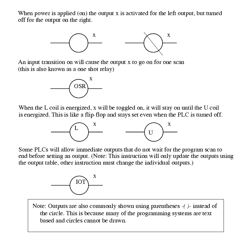
������������In ladder logic there are multiple types of outputs, but these are not consistently available on all PLCs. Some of the outputs will be externally connected to devices outside the PLC, but it is also possible to use internal memory locations in the PLC. Six types of outputs are shown in Figure 13. The first is a normal output, when energized the output will turn on, and energize an output. The circle with a diagonal line through is a normally on output. When energized the output will turn off. This type of output is not available on all PLC types. When initially energized the OSR (One Shot Relay) instruction will turn on for one scan, but then be off for all scans after, until it is turned off. The L (latch) and U (unlatch) instructions can be used to lock outputs on. When an L output is energized the output will turn on indefinitely, even when the output coil is deenergized. The output can only be turned off using a U output. The last instruction is the IOT (Immediate OutpuT) that will allow outputs to be updated without having to wait for the ladder logic scan to be completed.
Search for More: |

Custom Search
|
|