
|
|
|
28.1 INTRODUCTION
������������A computer with a single network interface can communicate with many other computers. This economy and flexibility has made networks the interface of choice, eclipsing point-to-point methods such as RS-232. Typical advantages of networks include resource sharing and ease of communication. But, networks do require more knowledge and understanding.
Small networks are often called Local Area Networks (LANs). These may connect a few hundred computers within a distance of hundreds of meters. These networks are inexpensive, often costing $100 or less per network node. Data can be transmitted at rates of millions of bits per second. Many controls system are using networks to communicate with other controllers and computers. Typical applications include;
Larger Wide Area Networks (WANs) are used for communicating over long distances between LANs. These are not common in controls applications, but might be needed for a very large scale process. An example might be an oil pipeline control system that is spread over thousands of miles.
28.1.1 Topology
������������The structure of a network is called the topology. Figure 420 shows the basic network topologies. The Bus and Ring topologies both share the same network wire. In the Star configuration each computer has a single wire that connects it to a central hub.
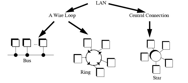
In the Ring and Bus topologies the network control is distributed between all of the computers on the network. The wiring only uses a single loop or run of wire. But, because there is only one wire, the network will slow down significantly as traffic increases. This also requires more sophisticated network interfaces that can determine when a computer is allowed to transmit messages. It is also possible for a problem on the network wires to halt the entire network.
The Star topology requires more wire overall to connect each computer to an intelligent hub. But, the network interfaces in the computer become simpler, and the network becomes more reliable. Another term commonly used is that it is deterministic, this means that performance can be predicted. This can be important in critical applications.
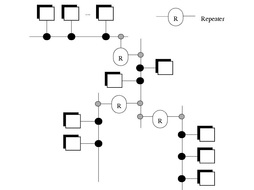
For a factory environment the bus topology is popular. The large number of wires required for a star configuration can be expensive and confusing. The loop of wire required for a ring topology is also difficult to connect, and it can lead to ground loop problems. Figure 421 shows a tree topology that is constructed out of smaller bus networks. Repeaters are used to boost the signal strength and allow the network to be larger.
28.1.2 OSI Network Model
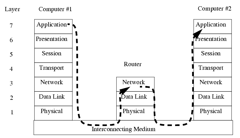
������������The Open System Interconnection (OSI) model in Figure 422 was developed as a tool to describe the various hardware and software parts found in a network system. It is most useful for educational purposes, and explaining the things that should happen for a successful network application. The model contains seven layers, with the hardware at the bottom, and the software at the top. The darkened arrow shows that a message originating in an application program in computer #1 must travel through all of the layers in both computers to arrive at the application in computer #2. This could be part of the process of reading email.
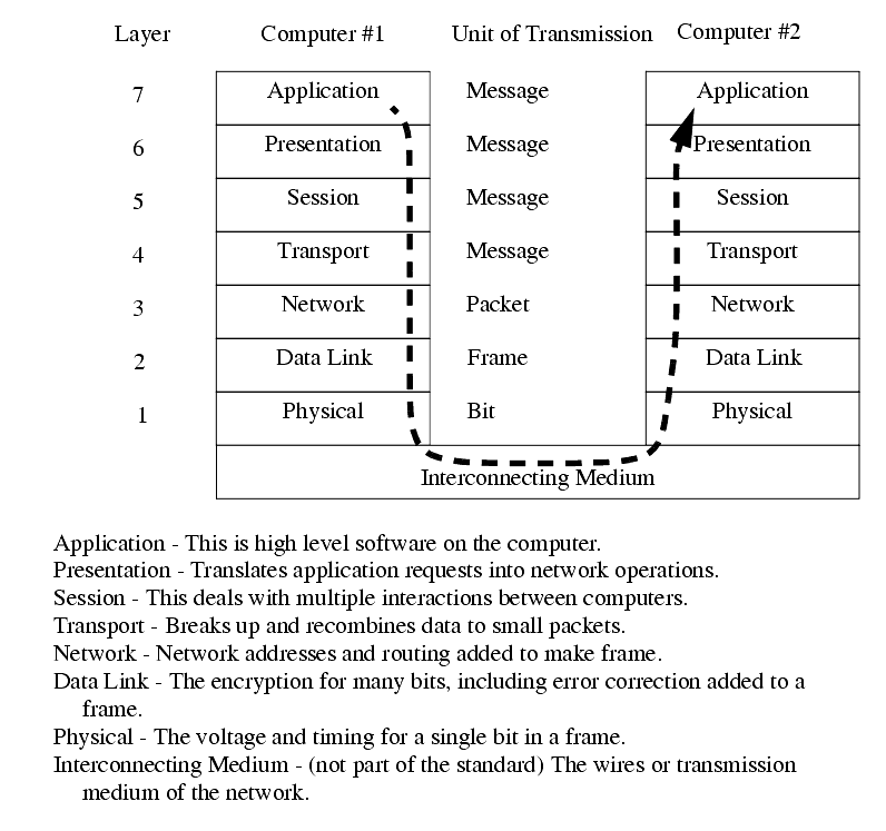
The Physical layer describes items such as voltage levels and timing for the transmission of single bits. The Data Link layer deals with sending a small amount of data, such as a byte, and error correction. Together, these two layers would describe the serial byte shown in the previous chapter. The Network layer determines how to move the message through the network. If this were for an internet connection this layer would be responsible for adding the correct network address. The Transport layer will divide small amounts of data into smaller packets, or recombine them into one larger piece. This layer also checks for data integrity, often with a checksum. The Session layer will deal with issues that go beyond a single block of data. In particular it will deal with resuming transmission if it is interrupted or corrupted. The Session layer will often make long term connections to the remote machine. The Presentation layer acts as an application interface so that syntax, formats and codes are consistent between the two networked machines. For example this might convert '\' to '/' in HTML files. This layer also provides subroutines that the user may call to access network functions, and perform functions such as encryption and compression. The Application layer is where the user program resides. On a computer this might be a web browser, or a ladder logic program on a PLC.
Most products can be described with only a couple of layers. Some networking products may omit layers in the model.
28.1.3 Networking Hardware
������������The following is a description of most of the hardware that will be needed in the design of networks.
Network Interface Hardware - The network interface may already be built into the computer/PLC/sensor/etc. These may cost $15 to over $1000.
10baseT (twisted pair) is the most popular. It is a pair of twisted copper wires terminated with an RJ-45 connector.
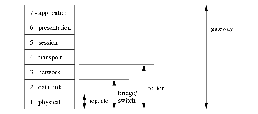
Repeaters (Physical Layer) - These accept signals and retransmit them so that longer networks can be built.
Hub/Concentrator - A central connection point that network wires will be connected to. It will pass network packets to local computers, or to remote networks if they are available.
Bridges (Data link layer) - These are intelligent devices that can convert data on one type of network, to data on another type of network. These can also be used to isolate two networks.
Gateway (Application Layer) - A Gateway is a full computer that will direct traffic to different networks, and possibly screen packets. These are often used to create firewalls for security.
Figure 423 shows the basic OSI model equivalents for some of the networking hardware described before.
28.1.4 Control Network Issues
������������A wide variety of networks are commercially available, and each has particular strengths and weaknesses. The differences arise from their basic designs. One simple issue is the use of the network to deliver power to the nodes. Some control networks will also supply enough power to drive some sensors and simple devices. This can eliminate separate power supplies, but it can reduce the data transmission rates on the network. The use of network taps or tees to connect to the network cable is also important. Some taps or tees are simple passive electrical connections, but others involve sophisticated active tees that are more costly, but allow longer networks.
The transmission type determines the communication speed and noise immunity. The simplest transmission method is baseband, where voltages are switched off and on to signal bit states. This method is subject to noise, and must operate at lower speeds. RS-232 is an example of baseband transmission. Carrierband transmission uses FSK (Frequency Shift Keying) that will switch a signal between two frequencies to indicate a true or false bit. This technique is very similar to FM (Frequency Modulation) radio where the frequency of the audio wave is transmitted by changing the frequency of a carrier frequency about 100MHz. This method allows higher transmission speeds, with reduced noise effects. Broadband networks transmit data over more than one channel by using multiple carrier frequencies on the same wire. This is similar to sending many cable television channels over the same wire. These networks can achieve very large transmission speeds, and can also be used to guarantee real time network access.
The bus network topology only uses a single transmission wire for all nodes. If all of the nodes decide to send messages simultaneously, the messages would be corrupted (a collision occurs). There are a variety of methods for dealing with network collisions, and arbitration.
CSMA/CD (Collision Sense Multiple Access/Collision Detection) - if two nodes start talking and detect a collision then they will stop, wait a random time, and then start again.
CSMA/BA (Collision Sense Multiple Access/Bitwise Arbitration) - if two nodes start talking at the same time the will stop and use their node addresses to determine which one goes first.
Master-Slave - one device one the network is the master and is the only one that may start communication. slave devices will only respond to requests from the master.
Token Passing - A token, or permission to talk, is passed sequentially around a network so that only one station may talk at a time.
The token passing method is deterministic, but it may require that a node with an urgent message wait to receive the token. The master-slave method will put a single machine in charge of sending and receiving. This can be restrictive if multiple controllers are to exist on the same network. The CSMA/CD and CSMA/BA methods will both allow nodes to talk when needed. But, as the number of collisions increase the network performance degrades quickly.
Search for More: |

Custom Search
|

|