11.3 SEQUENCE BITS
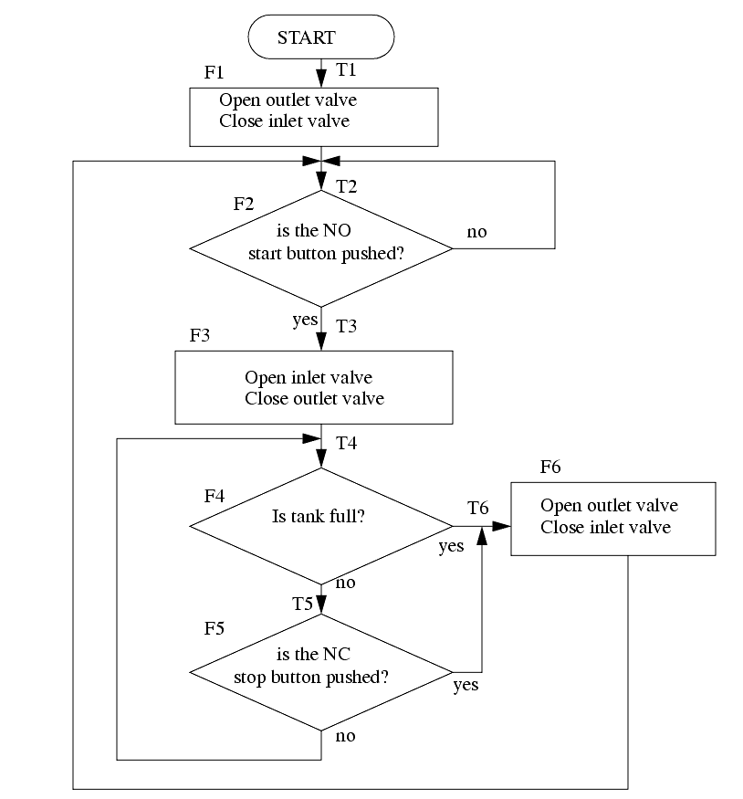
������������In general there is a preference for methods that do not use MCR statements or latches. The flowchart used in the previous example can be implemented without these instructions using the following method. The first step to this process is shown in Figure 135. As before each of the blocks in the flowchart are labelled, but now the connecting arrows (transitions) in the diagram must also be labelled. These transitions indicate when another function block will be activated.

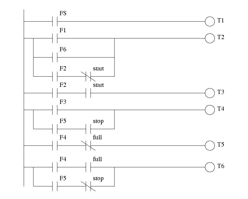
The first section of ladder logic is shown in Figure 136. This indicates when the transitions between functions should occur. All of the logic for the transitions should be kept together, and appear before the state logic that follows in Figure 137.

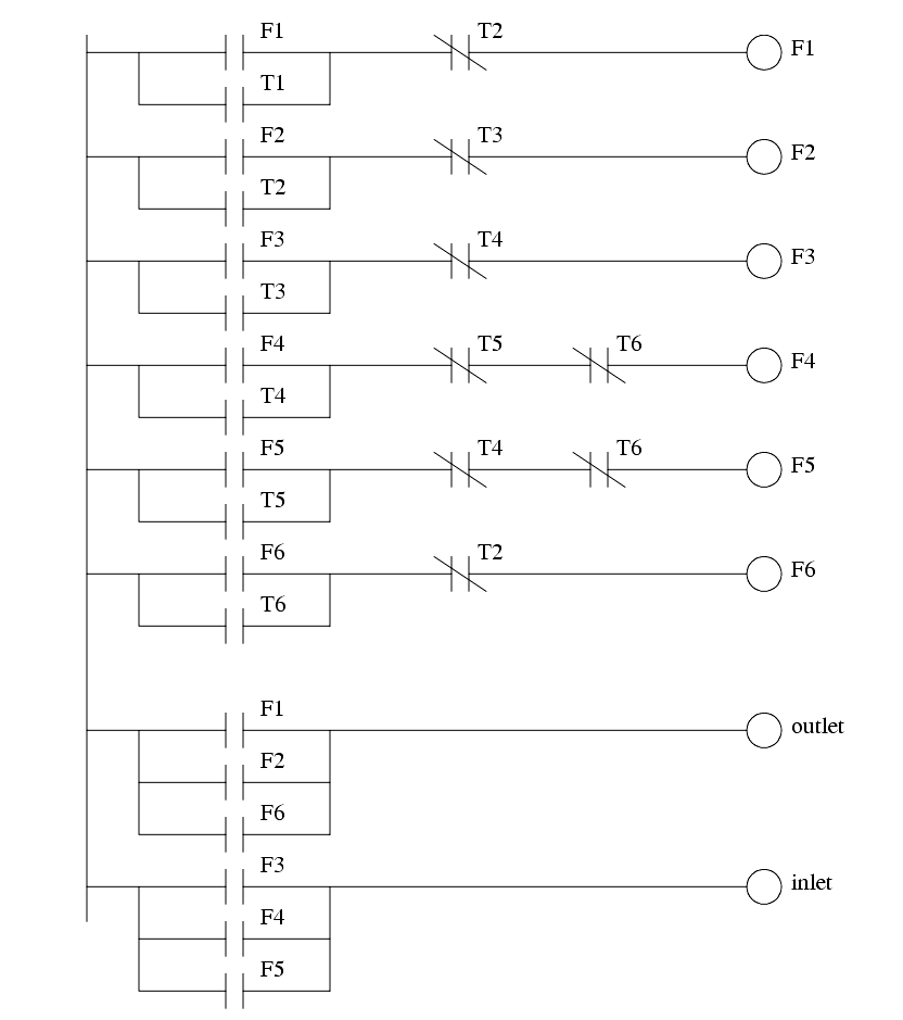
The logic shown in Figure 137 will keep a function on, or switch to the next function. Consider the first ladder rung for F1, it will be turned on by transition T1 and once function F1 is on it will keep itself on, unless T2 occurs shutting it off. If T2 has occurred the next line of ladder logic will turn on F2. The function logic is followed by output logic that relates output values to the active functions.
