
|
|
|
30.2 ELECTRICAL WIRING DIAGRAMS
������������In an industrial setting a PLC is not simply "plugged into a wall socket". The electrical design for each machine must include at least the following components.
A control system will normally use AC and DC power at different voltage levels. Control cabinets are often supplied with single phase AC at 220/440/550V, or two phase AC at 220/440Vac, or three phase AC at 330/550V. This power must be dropped down to a lower voltage level for the controls and DC power supplies. 110Vac is common in North America, and 220Vac is common in Europe and the Commonwealth countries. It is also common for a controls cabinet to supply a higher voltage to other equipment, such as motors.
An example of a wiring diagram for a motor controller is shown in Figure 439 (note: the symbols are discussed in detail later). Dashed lines indicate a single purchased component. This system uses 3 phase AC power (L1, L2 and L3) connected to the terminals. The three phases are then connected to a power interrupter. Next, all three phases are supplied to a motor starter that contains three contacts, M, and three thermal overload relays (breakers). The contacts, M, will be controlled by the coil, M. The output of the motor starter goes to a three phase AC motor. Power is supplied by connecting a step down transformer to the control electronics by connecting to phases L2 and L3. The lower voltage is then used to supply power to the left and right rails of the ladder below. The neutral rail is also grounded. The logic consists of two push buttons. The start push button is normally open, so that if something fails the motor cannot be started. The stop push button is normally closed, so that if a wire or connection fails the system halts safely. The system controls the motor starter coil M, and uses a spare contact on the starter, M, to seal in the motor stater.
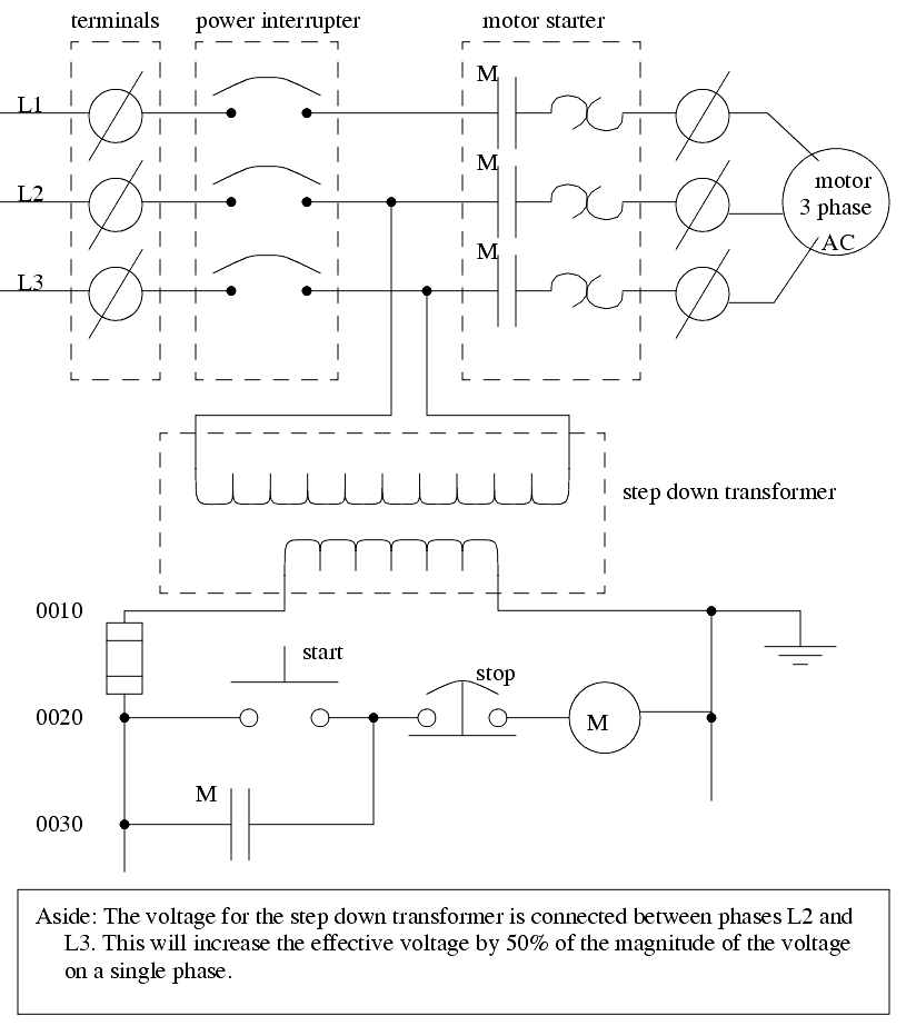
The diagram also shows numbering for the wires in the device. This is essential for industrial control systems that may contain hundreds or thousands of wires. These numbering schemes are often particular to each facility, but there are tools to help make wire labels that will appear in the final controls cabinet.
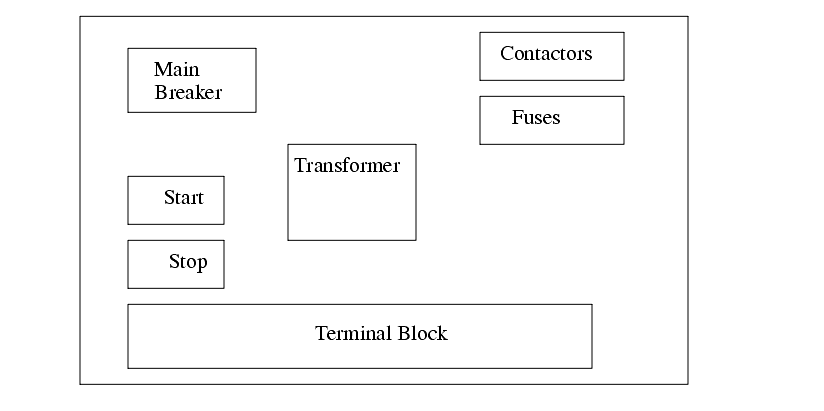
Once the electrical design is complete, a layout for the controls cabinet is developed, as shown in Figure 440. The physical dimensions of the devices must be considered, and adequate space is needed to run wires between components. In the cabinet the AC power would enter at the terminal block, and be connected to the main breaker. It would then be connected to the contactors and fuses. Two of the phases are also connected to the transformer to power the logic. The start and stop buttons are at the left of the box (note: normally these are mounted elsewhere, and a separate layout drawing would be needed).
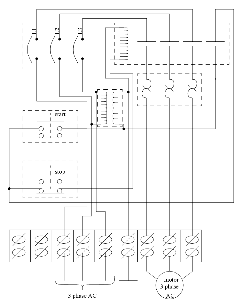
The final layout in the cabinet might look like the one shown in Figure 441.
When being built the system will follow certain standards that may be company policy, or legal requirements. This often includes items such as;
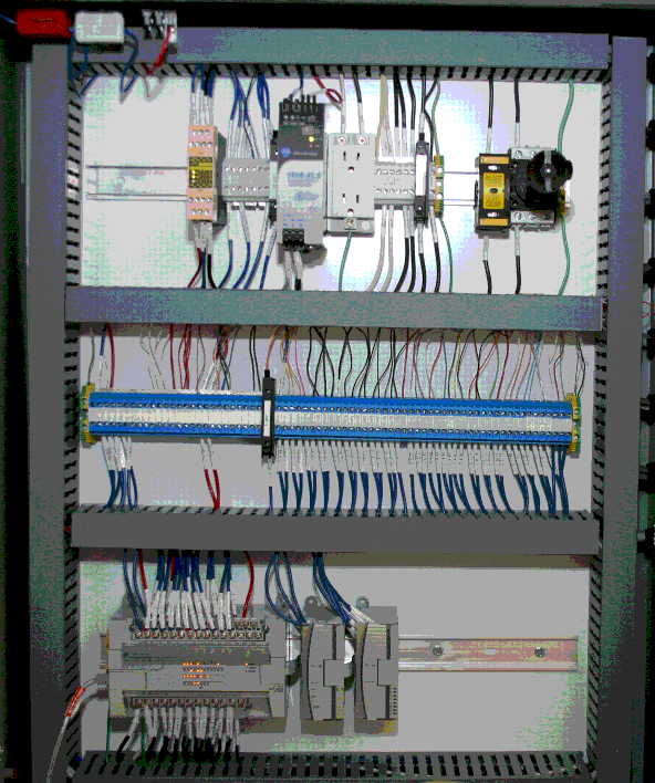
A photograph of an industrial controls cabinet is shown in Figure 442.
30.2.1 Selecting Voltages
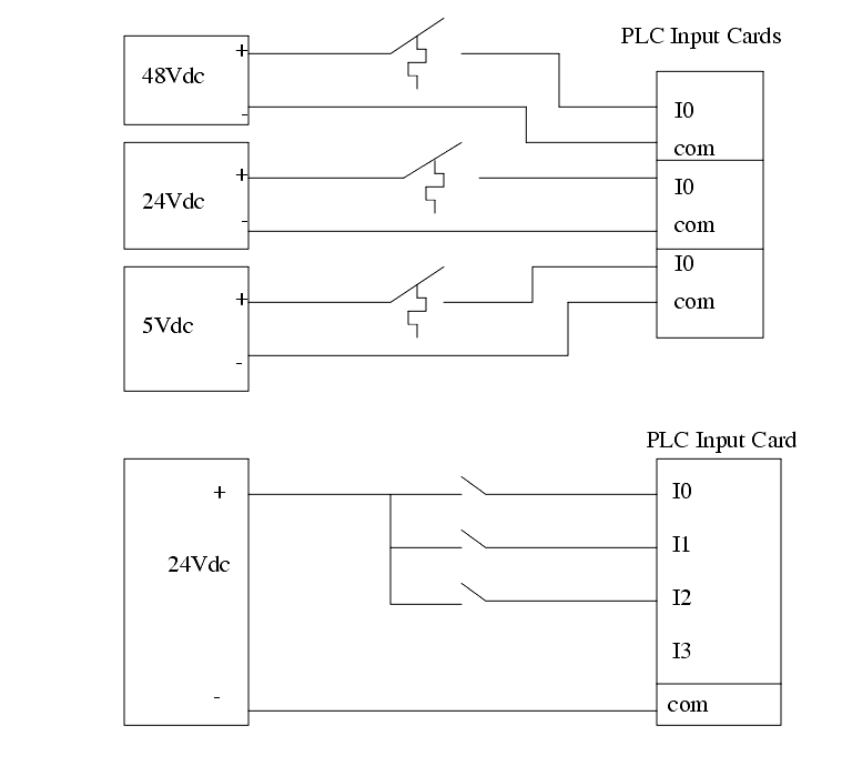
������������When selecting voltage ranges and types for inputs and outputs of a PLC some care can save time, money and effort. Figure 443 that shows three different voltage levels being used, therefore requiring three different input cards. If the initial design had selected a standard supply voltage for the system, then only one power supply, and PLC input card would have been required.
30.2.2 Grounding
������������The terms ground and common are often interchanged (I do this often), but they do mean different things. The term, ground, comes from the fact that most electrical systems find a local voltage level by placing some metal in the earth (ground). This is then connected to all of the electrical outlets in the building. If there is an electrical fault, the current will be drawn off to the ground. The term, common, refers to a reference voltage that components of a system will use as common zero voltage. Therefore the function of the ground is for safety, and the common is for voltage reference. Sometimes the common and ground are connected.
The most important reason for grounding is human safety. Electrical current running through the human body can have devastating effects, especially near the heart. Figure 444 shows some of the different current levels, and the probable physiological effects. The current is dependant upon the resistance of the body, and the contacts. A typical scenario is, a hand touches a high voltage source, and current travels through the body and out a foot to ground. If the person is wearing rubber gloves and boots, the resistance is high and very little current will flow. But, if the person has a sweaty hand (salty water is a good conductor), and is standing barefoot in a pool of water their resistance will be much lower. The voltages in the table are suggested as reasonable for a healthy adult in normal circumstances. But, during design, you should assume that no voltage is safe.


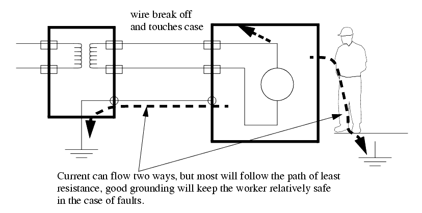
Figure 445 shows a grounded system with a metal enclosures. The left-hand enclosure contains a transformer, and the enclosure is connected directly to ground. The wires enter and exit the enclosure through insulated strain reliefs so that they don't contact the enclosure. The second enclosure contains a load, and is connected in a similar manner to the first enclosure. In the event of a major fault, one of the "live" electrical conductors may come loose and touch the metal enclosure. If the enclosure were not grounded, anybody touching the enclosure would receive an electrical shock. When the enclosure is grounded, the path of resistance between the case and the ground would be very small (about 1 ohm). But, the resistance of the path through the body would be much higher (thousands of ohms or more). So if there were a fault, the current flow through the ground might "blow" a fuse. If a worker were touching the case their resistance would be so low that they might not even notice the fault.

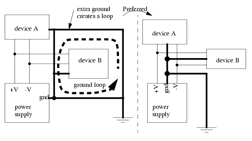
When improperly grounded a system can behave erratically or be destroyed. Ground loops are caused when too many separate connections to ground are made creating loops of wire. Figure 446 shows ground wires as darker lines. A ground loop caused because an extra ground was connected between device A and ground. The last connection creates a loop. If a current is induced, the loop may have different voltages at different points. The connection on the right is preferred, using a tree configuration. The grounds for devices A and B are connected back to the power supply, and then to the ground.
Problems often occur in large facilities because they may have multiple ground points at different end of large buildings, or in different buildings. This can cause current to flow through the ground wires. As the current flows it will create different voltages at different points along the wire. This problem can be eliminated by using electrical isolation systems, such as optocouplers.
When designing and building electrical control systems, the following points should prove useful.
- Each PLC component should be grounded back to the main PLC chassis. The PLC chassis should be grounded to the backplate.
- Use 12AWG stranded copper for PLC equipment grounds and 8AWG stranded copper for enclosure backplate grounds.
30.2.3 Wiring
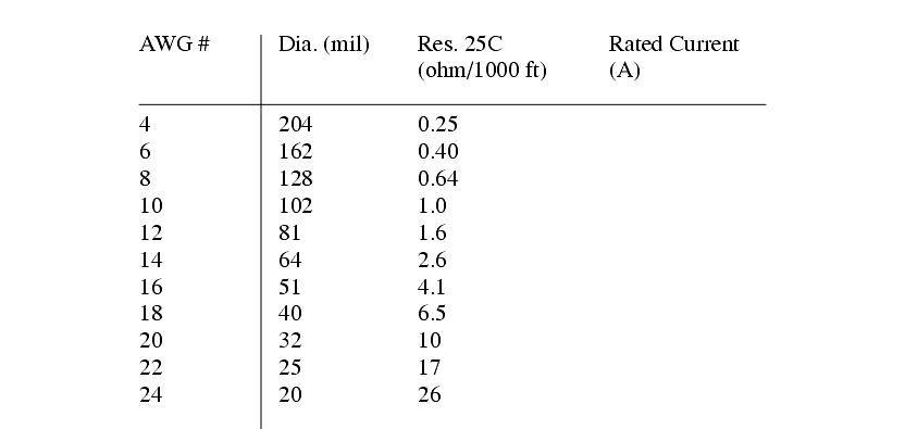
������������As the amount of current carried by a wire increases, it is important to use a wire with a larger cross section. A larger cross section results in a lower resistance, and less heating of the wire. The standard wire gages are listed in Figure 447.
30.2.4 Suppressors
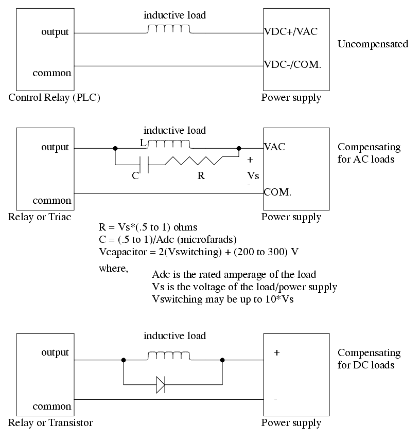
������������Most of us have seen a Vandegraff generator, or some other inductive device that can generate large sparks using inductive coils. On the factory floor there are some massive inductive loads that make this a significant design problem. This includes devices such as large motors and inductive furnaces. The root of the problem is that coils of wire act as inductors and when current is applied they build up magnetic fields, requiring energy. When the applied voltage is removed and the fields collapse the energy is dumped back out into the electrical system. As a result, when an inductive load is turned on it draws an excess amount of current (and lights dim), and when it is turn it off there is a power surge. In practical terms this means that large inductive loads will create voltage spikes that will damage our equipment.
Surge suppressors can be used to protect equipment from voltage spikes caused by inductive loads. Figure 448 shows the schematic equivalent of an uncompensated inductive load. For this to work reliably we would need to over design the system above the rated loads. The second schematic shows a technique for compensating for an AC inductive load using a resistor capacitor pair. It effectively acts as a high pass filter that allows a high frequency voltage spike to be short circuited. The final surge suppressor is common for DC loads. The diode allows current to flow from the negative to the positive. If a negative voltage spike is encountered it will short circuit through the diode.
30.2.5 PLC Enclosures
������������PLCs are well built and rugged, but they are still relatively easy to damage on the factory floor. As a result, enclosures are often used to protect them from the local environment. Some of the most important factors are listed below with short explanations.
Dirt - Dust and grime can enter the PLC through air ventilation ducts. As dirt clogs internal circuitry, and external circuitry, it can effect operation. A storage cabinet such as Nema 4 or 12 can help protect the PLC.
Humidity - Humidity is not a problem with many modern materials. But, if the humidity condenses, the water can cause corrosion, conduct current, etc. Condensation should be avoided at all costs.
Temperature - The semiconductor chips in the PLC have operating ranges where they are operational. As the temperature is moved out of this range, they will not operate properly, and the PLC will shut down. Ambient heat generated in the PLC will help keep the PLC operational at lower temperatures (generally to 0°C). The upper range for the devices is about 60°C, which is generally sufficient for sealed cabinets, but warm temperatures, or other heat sources (e.g. direct irradiation from the sun) can raise the temperature above acceptable limits. In extreme conditions heating, or cooling units may be required. (This includes "cold-starts" for PLCs before their semiconductors heat up).
Shock and Vibration - The nature of most industrial equipment is to apply energy to change workpieces. As this energy is applied, shocks and vibrations are often produced. Both will travel through solid materials with ease. While PLCs are designed to withstand a great deal of shock and vibration, special elastomer/spring or other mounting equipment may be required. Also note that careful consideration of vibration is also required when wiring.
Power - Power will fluctuate in the factory as large equipment is turned on and off. To avoid this, various options are available. Use an isolation transformer. A UPS (Uninterruptable Power Supply) is also becoming an inexpensive option, and are widely available for personal computers.
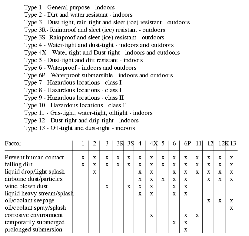
A standard set of enclosures was developed by NEMA (National Electric Manufacturers Association). These enclosures are intended for voltage ratings below 1000Vac. Figure 449 shows some of the rated cabinets. Type 12 enclosures are a common choice for factory floor applications.
30.2.6 Wire and Cable Grouping
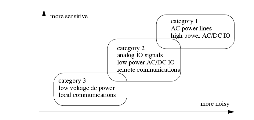
������������In a controls cabinet the conductors are passed through channels or bundled. When dissimilar conductors are run side-by-side problems can arise. The basic categories of conductors are shown in Figure 450. In general category 1 conductors should not be grouped with other conductor categories. Care should be used when running category 2 and 3 conductors together.
Search for More: |

Custom Search
|

|