8. Product ModellingThe role of this chapter is to provide a description of how products will be modelled for use in subsequent sections of the thesis. The representation is similar to other approaches, but has some subtle differences to support the subsequent planning process. This is not to say that the method is a replacement of previous methods, in fact it may be used to imitate many of the other methods available. The description begins with a review of solid modelling as it applies to product modelling. This is followed by some discussion of how to incorporate not only solid modelling, but other aspects of product design, into an algebraic form. Software implementations were used for verification of the method. These include capabilities for storage of arbitrary sets, and storage and manipulation of Boolean equations. If the reader requires more background in solid modeling, they are directed to Requicha and Rossignac [1992] and Stewart [1990]. Requicha [1992] asserts that there are three fundamental methods for representing solid objects: Decomposition, Boundaries, and Construction. Decomposition uses representations which attempt to divide space in some discrete manner. These approaches include thin 2 dimensional slices, voxels, ray casting, oct-trees, and binary space partition trees. Boundary methods use the faces, edges, and vertices of the object. Various data structures differentiate much of the work in this field. Requicha [1992] also states that additional information is required with the boundaries to establish solid properties. Finally, Constructive approaches build up the data representation from other geometries. The most popular constructive techniques are the CSG (Constructive Solids Geometry) and Sweeping methods. There are clear differentiations between each of the three main solid modelling approaches. The Constructive methods are well defined volumes, whereas the other methods are subject to spatial resolution, volume location and data abstraction problems. For example the CSG method is described by Requicha as “rooted, directed, acyclic, binary graphs, where the internal nodes correspond to Boolean operations or rigid-body transformations and where leaves are primitive bounded solids or half spaces. CSG representations are concise, always valid in the r-set modeling domain, and easily parameterized and edited.” Higher level methods for representing solids have also been examined in recent research. One particular method often cited is feature modelling. In this approach the part is described with features. The features are treated as solids, and operated upon as solids [ElMaraghy, 1991]. In addition to problems mentioned in the last chapter, a problem it causes for Solid Modeling is that when features overlap there is no method for determining priority [Requicha, 1992]. For example, if a fillet overlaps a hole, does the fillet cover the hole, or is it removed? The CSG representation has been chosen for this thesis because it is both abstract and unambiguous. This makes it well suited to serve as the basis for this reasoning system. More specifically the representation will be done with the CSG expressions in Boolean form. An analytic expression of geometry can provide an exact representation of a part. As the geometry of the part is analyzed, it may be decomposed into boundaries, then surfaces, and finally lines. At each interpretation some information is lost. Boolean operations on sets are the most abstract representation of solids, with the least detail. By its nature the CSG representation is informationally complete, concise, and the method of representation ensures syntactic correctness. Constructive Solid Geometry (CSG) is an explicit mathematical representation. The geometry may be expressed as a Boolean equation with sets as the variables. This means there are a number of basic properties that are of relevance to any work using these equations. This section of the chapter will address the basic properties and relationships of interest. 8.3.1 Basic ConceptsCSG models are based upon Boolean operations performed on primitive solids. Many names have been given to this method, for example Constructive Solids Geometry (CSG) and the Set Theoretic method. There are also many basic representations that may be used. One is the CSG tree, which is a combination of operations and primitives as seen in Figure 8.1 CSG Representation in Tree and Expression Form. The nodes of the tree are operations, and the leaves of the tree are primitives. There are only two children for each node. The top of the tree is referred to as the root. Another method for representation is in expression form. The expression form uses operators applied to the variables, which represent the primitives (see Lee and Jea [1988] for more examples). Other deviations on the expressions have been developed by various researchers, such as Woo [1977]. He uses a similar expression structure, but each term has the same operator applied to all of the variables within the set of brackets. 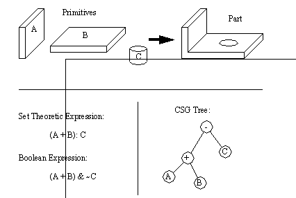
Figure 8.1 CSG Representation in Tree and Expression Form Some of the distinctive features of CSG models are globalness, non-uniqueness, and redundancy. The term ‘global’ refers to the possible distribution of solids over a tree, or an expression, whatever the case. There have been attempts to overcome this by using normal [Goldfeather et. al., 1986] and canonical [Kakaza and Okino, 1984] forms. Although these methods may still leave distributed terms, they do reduce the distribution. The non-uniqueness property refers to the infinite number of ways in which specific solid geometries may be composed. This is still an ongoing research problem. Some authors [Woodwark, 1988] view this as a major problem for CSG when finding a single set of manufacturing features for a part. But, as the reader will see, I have exploited this to find many alternative manufacturing features for production. The redundancy problem builds upon the non-uniqueness. In this case there are two primitives that cancel each other. Tilove [1984] gives as an example a CSG tree where the designer has used a cylinder to fill a previously cut hole. To solve this problem Tilove [1984] developed algorithms for Null Object Detection (NOD), to determine when there are redundant primitives. 8.3.2 Set Topology (Unary Operators)A set topology is considered to be a set of points in space. By definition, these points do not include a boundary. The standard topological operators are complement, interior, closure and boundary. These unary operators differ from the binary operators in that they only operate on one set. 8.3.3 Binary OperatorsWhen dealing with two interacting topologies, binary operators are required to describe the interaction. The commonly used operators are union (OR), intersection (AND) and difference (AND with NOT). If these operators are applied with ignorance to the point sets there are possible overlap and singular contact point problems. When these binary operators are used in combination with the unary operators the result is a theoretically correct and complete set of operators. These are described in the next section. 8.3.4 Set Theoretic OperatorsThe basic operators were described before, and there are other enhanced operators such as Assemble [Arbab, 1990] [Hartquist and Marisa, 1985]. These operators work on basic sets of topological primitives. The primitives can be represented in a few different forms. The traditional approach uses r-sets [Requicha, 1980] and a newer approach uses s-sets [Arbab, 1990]. An r-set [Tilove and Requicha, 1980] is used to represent a homogenous solid in three dimensional Euclidean space. The face of the solids is assumed to be rational, therefore there are no unassociated vertices, edges, faces. This also implies no infinitely thin holes or cracks. The volumes must be enclosed by a set of boundaries. The set is closed, which means that it includes its own boundary. The set is also regular which means it is equal to the closure of its interior. And, the set is semianalytic, which means it can be expressed as a finite boolean combination of analytic sets. When operations are done they may not result in a set which is closed and regular. Therefore, a special set of operators have been developed which force a closed regular object. These are the Regularized operators. When applied these operators will eliminate dangling planes, vertices, edges, infinitely small holes and cracks. The definitions of these operators is given in Figure 8.2 Axioms of r-sets (These ensure that all sets are closed, and regular). The r-set approach is not always desirable. When dealing with assemblies, non-manifold contact r-sets would call for physically connected parts. But, it may be desired to have parts that are physically separate, such as press fits. [Aside: manifold solids have edges bounding exactly two faces, and vertices acting as a point of a cone. Nonmanifold parts touch with one or both parts along points, or edges only, therefore not sharing any volume at the point of contact. In more practical terms, nonmanifold objects can erroneously suggest that part of an object exists without any volume]. 
Figure 8.2 Axioms of r-sets (These ensure that all sets are closed, and regular) One simple method of allowing touching parts is to use an assembly operator, this allows aggregates of r-sets (each part in the assembly is stored separately). PADL2 [Hartquist and Marisa, 1985] uses these sets to represent assemblies. Extended CSG trees are used to represent Assembly operators, along with Regularized Boolean operators. The axioms in Figure 8.3 Axioms for Assembly Operators are for assembly operators, and will permit us to manipulate the individual assemblies, without forcing them to join. Arbab [1990] discusses the use of the Assembly operator, and likens it to a placeholder in the CSG trees. This method cannot derive a single r-set, thus a re-evaluation is required whenever a new operator is applied. Also, because the sets are stored separately, mathematical errors may accumulated differently and result in slight variations in object positions after transformations. 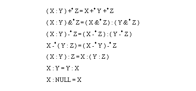
Figure 8.3 Axioms for Assembly Operators When dealing with assemblies, an alternative to r-sets and Assembly operators are open regular sets. These sets have all of the properties of the r-sets, except that points on the boundary are not considered part of the volume. This allows surfaces to make contact, without having to become a single solid [Arbab, 1991]. This method does not allow internal nonmanifold boundaries. To allow internal boundaries, hypersets may be used [Requicha, 1992]. A volume set is decomposed into volume subsets (hypersets) which are the result of previous set operations that have resulted in the nonhomogenous solid. Arbab [1990] proposes s-sets as an alternative to r-sets, Assembly operators, and open regular sets. The essential feature of this method is that separate internal boundaries are allowed within the solids. An assembly operator is an inherent part of s-sets. The basic s-set operators are shown in Figure 8.4 Open Regular Axioms for s-sets. Note that the assembly operator only acts when the components do not intersect in the first intersection axiom. A preferred approach to the assembly axiom is also provided that will split the assembled volume into three components. The internal boundaries are not preserved by all operations, only the assembly operation may create new internal boundaries. Arbab also poses a set of axioms specifically for a B-Rep of s-sets. 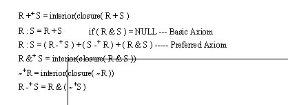
Figure 8.4 Open Regular Axioms for s-sets The methods previously described are concerned with exact representations of solids. In actuality, solids never conform exactly to a geometrical form. Variational classes have been introduced as a method for dealing with sets of acceptable tolerances for solids [Requicha, 1992]. In the authors opinion the most flexible approach which has been developed is Selective Geometry Complexes (SGC). This method uses aggregates of mutually disjoint cells that are connected in a continuous geometry. The sets can be open or closed, and the geometry expressed in equation form. For example, a union of two shapes could result in one solid, containing three separate volume regions. Where the two solids touched, an unknown volume would now exist, hence the three regions are required. Rossignac and Requicha [1991] developed a new representation scheme called Constructive Non-Regularized Geometry (CNRG) which takes advantage of previous set operations, including SGC. In total, their representation scheme allows all of the previous regularized operations, as well as nonhomogenous solids (materials with varying properties), and assemblies. This method is very exciting, and would be excellent for representing the solids commonly found in design. Unfortunately, at the time of writing, this work was still under development, and not in a suitable state for use. The previous discussion indicates that there are many methods for modelling solids in a set theoretic approach. It also indicates that there are no ‘perfect’ methods yet. As a result it was decided that the design representation should be as abstract as possible, to ensure conformity to whatever method is developed. In practical terms this means that the Assembly operator will be maintained as an independent operator keeping all of the geometries separate. This is most similar to the r-set approach. Eventually, new operators for assembly can be added when the tools to support them are available. It was decided to use the non-uniqueness and global nature of the CSG representation to drive the logic of the BCAPP planning system. But, in addition to this the CSG expression will be represented with Boolean expressions to allow use of Boolean algebra. This section will describe my particular representation. The following sections will discuss implementation of this representation in a Boolean Algebra program, and representing product designs with Boolean equations of sets. First, while the scope of operators is clearly defined in Boolean algebra, they can be somewhat confusing to comprehend. The problem of changing operator scope will require that any computer program understand the rules for their application. This would require some form of complex algorithm to determine operator scope before the simplest operation could be performed. To simplify this problem a Nested Boolean form is adopted which is very scope specific, similar to that used in Woo[1977]. This form puts each operator in a set of brackets. As in normal algebra, nested terms in brackets must be performed first. This method does not in any way restrict the use of any of the Boolean operators, but removes any question of ambiguity in interpretation. A detailed discussion will follow, but an example of this is, ( + ( * A B ) ( * A ( ~ C ) ) ) (3.2) While the first equation above would require some interpretation as to order, the second form specifies that the NOT operation, and the AND operations must be performed before the OR operation. The only addition is the generous use of brackets, and the collection of an operator over a list of terms. In a more logical form the equality of both representations may be shown by first considering the premise that precedence of operations in an expression is directly based upon either conventions of priority for operations, or precedence that is clearly indicated by bracketed terms. Therefore, when considering the conventional precedence of operators, a high priority operator would be forced to occur first, as if it were in brackets. When brackets are used anyway, they duplicate the brackets in the Nested Boolean representation. Secondly, because of the nature of design, we would attempt to economize on effort by reusing terms, and sets. As is seen in the expression above (3.2), A is reused in the same equation. Say for example that A is a common screw. In the equation above it would be used twice. The problem arises in that the set that defines the geometry of the screw, also defines attributes such as position. In the representation above, both of the screws would overlap in space. This assertion is obviously nonsense, so to overcome it, enhancements were added to the equations. These come in the form of attribute sets that may be appended to any symbol, or term in an equation. An example is seen below, ( + ( * A;move_to_B B ) ( * A;Fixture ( ~ C );Move_to_A );Move_to_spot ) In this case some terms and symbols have been augmented with additional property sets that effectively become part of the original set. Therefore in this case we have defined only one A, but after adding ‘move_to_B’ to one, and ‘Move_to_A’ to the other, they now become separate, and individual sets. This starts to explore the subtle differences of equations of sets to be discussed later. Thirdly, the exclusive use of Boolean operators is not realistic here because of the use of sets, and the irrationality of product representation. Therefore the Boolean operators have been supplemented with some other operators and constraints. As discussed before, assemblies are difficult to model within one solid model. As a result we use the assembly operator used in many solid modelers. This allows parts which may overlap in a geometrical model (e.g., a press fit) to coexist separately. This also allows the designer to specify when an assembly is actually desired. 8.5.1 A File Format for Product DescriptionWhile the mathematical descriptions in the previous section outlined the theoretical model of the product, it was necessary to describe the part in some file format for verification of the method, and for other stages of testing. The file format chosen was a text format, which would allow easy editing and verification. A sample of the file format is shown in Figure 8.5 A Sample File Defining a Part. Within the file the sets are defined by giving the set name, and then a list of properties, delimited by the ‘{‘ and ‘}’ brackets. All of the properties are arbitrary, except for the ‘EQUATION’ property. The purpose of the ‘EQUATION’ property is to indicate how other sets combine into this one. This format has been left particularly loose, so as to not restrict future development. The problems with fixed fields are emphasized by the number of special cases required for small differences, as can be seen in vonRimscha [1989]. One potential problem that could result from the free form representation is the inadvertent creation of a recursive reference for a child to a parent, which is physically impossible. Within my thesis I will use a few properties that can be considered standard, such as ‘translate_y’. Most of the attributes will be easy to identify from their name only. The selection of properties should be done on an application specific basis. A readily available example of this is, that by choosing ‘translate_y’ we assume all coordinates are Cartesian, whereas we may have a robotics based design which considers cylindrical coordinates the norm, such as ‘translate_r’. A number of properties have been identified in other work that must be stored in addition to the basic solid model for completeness. Some of these other properties are tolerances and material [Braid, 1986]. The file below is one of the test files used to verify the software written. It depicts a nut and bolt assembly (as indicated by the ‘main’ classifier). Notably, this set only contains an equation. In a practical use this would probably contain some information from the designer. The expression contains a Boolean equation that refers to ‘nut’, and to ‘bolt’. And, the set ‘bolt’ is modified by adding ‘move_to_hole’. The ‘move_to_hole’ set is now appended onto the ‘bolt’ set for the assembly operation. EQUATION: ( + C ( & D;test1 ( ~ E ) ) Figure 8.5 A Sample File Defining a Part This particular structure can be of use because the process planner in not just receiving geometry, but also some insight to the designers methodology. For example, the assembly of the nut and bolt in a traditional solid model would just be two separate non-overlapping geometries. In this model we can clearly (and easily) identify the two separate parts that are assembled. The file format not only represents the final geometry, but the designer’s perceptions of the design. When the file format is loaded it can be easily interpreted into a Boolean equation. The example below uses substitution to expand the equation in the main set to a final geometric description. ( : nut bolt;move_to_hole ) (3.3) ( : ( & A ( ~ B ) ) bolt;move_to_hole ) (3.4) ( : ( & A ( ~ B ) ) ( + C ( & D;test1 ( ~ E ) ) );move_to_hole ) (3.5) The final equation is of the type that can be used to drive a solid modeler. The figure below was automatically generated from the ‘nut_and_bolt’ file above, and coincidently also helped verify the correctness of the low level boolean algebra routines. 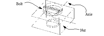
Figure 8.6 The ‘nut_and_bolt’ Example Interpreted into Geometry (modelled rendered using ACIS [Spatial Technology, 1991]) The representation here was developed to facilitate testing of the system. In review it is safe to say that this system could eventually benefit by the incorporation of a more formal language structure, such as that of PDL [H. A. ElMaraghy, 1991], or ALPS [Mantyla, 1993]. The Boolean algebra methods described in this thesis are supported by a set of Boolean algebra data structures. These structures were written in C++, thus there is some use of inheritance, and functions are associated with the Boolean data structure [Strousap, 1986]. 8.6.1 Data Structures for Boolean Equation StorageAs shown before, each term is represented in a LISP like fashion with an operator being first in the list, followed by a list of operands. An example of this equation form is shown in Figure 8.7 Nested Boolean Algebra Data Structure (Only a partial example is given for clarity), along with a data structure diagram that is used to store the equation (only part of the equation is shown for the purpose of clarity). The Operation List may be thought of as storing the start of each nested term, it coincides with the open bracket ‘(‘ and the operator. Therefore, each operator is assigned a row. The row points to a list of terms. The other field in the row is for a symbol pointer. The Symbol Pointer allows a text string (and other symbol information) to be associated with each operation. The append list field allows lists of appended properties, such as ‘test’, to be appended to symbols and terms. The Term Lists array is simply for storing lists of arguments for the operations. The reader will note that the pointer refers to both the Operation List, and the Symbol List. This allows both sets, like ‘A’ and sub-terms ‘(+ D G)’ to exist in common. The ‘type’ field specifies which type of pointer is in the ‘pointer’ field. The ‘point to next’ field provides a linked list of the arguments, and terminates with a ‘last’ marker. Finally, the Symbol list is used to store textual information for recall by the user. These also contain two fields for use by the calling routines. A ‘pointer’ field is provided so that the user may store a reference to an outside object (like a geometric primitive), whereas a ‘type’ field provides information about the pointer type. There are additional types of data associated with each list for the purposes of maintenance, as is described on the next paragraph. 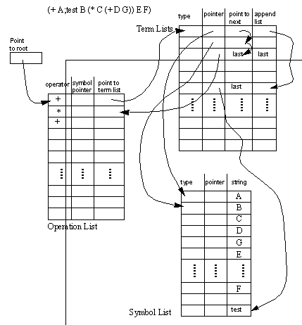
Figure 8.7 Nested Boolean Algebra Data Structure (Only a partial example is given for clarity) The reader should note that the data structures in Figure 8.7 Nested Boolean Algebra Data Structure (Only a partial example is given for clarity) do not show the method for dynamic memory allocation. The lists shown in the data structure have many rows which will be added and deleted in a semi-random fashion. As a result, a reuse mechanism structure has developed for each of the lists. One example of this structure is shown in Figure 8.8 Dynamic Memory Structures Added to Lists, and may be viewed as a generic approach for all of the lists above. In Figure 8.7 Nested Boolean Algebra Data Structure (Only a partial example is given for clarity) both ‘used’ and ‘point to next’ are added data fields. This structure makes allocation of a new row, simply a matter of deleting from the head of empty linked list, and pushing onto the head of the used list. Deletion of an existing term is a case of modifying next pointers to point over the defunct term, then pushing the now empty term onto the empty list. The used and unused flags are updated to make validity checking easier, without having to retrace lists. The end of list pointer makes range checking easy, when the array has been dynamically allocated (as was done using C++). 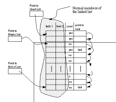
Figure 8.8 Dynamic Memory Structures Added to Lists Public functions have been created to manipulate each object. These are structured so that the functionalities are nested. Some of the functions are listed below. List/Count terms/symbols in an equation.This list has many functions, but as a group they enable storage, and manipulation of boolean expressions. When referring to individual terms/symbols in the expression their location may be addressed by a simple scheme. For example, the address ‘:2:2:2’ in the equation ‘(+ A B ( * C D (+ E F G H)’ would refer to the symbol ‘G’. For the same equation, address ‘:2’ (or ‘:2:’) would refer to the term ‘( * C D (+ E F G H ) )’, and address ‘:’ refers to the entire equation. This lays the ground work for a systematic addressing of the equation for boolean algebra. Once an equation has been stored in the Boolean Equation data structures, it need to be manipulated. This can be done by examining the rules of Boolean algebra, and then casting these in the form of algorithmic operations. 8.7.1 Previous Work in Manipulation of Boolean EquationsLee and Jea [1988] discuss a method for manipulating the structure of a CSG tree by moving branches up and down the tree structure. They limit the operators to union and subtraction, and assume the operators are regularized. They argue that for feature recognition using CSG, it is necessary to move nodes up the CSG tree to be compared. Although they do not pose a feature recognition algorithm, they do suggest that various nodes may be moved up the CSG to partially overcome the global, and uniqueness problems of the CSG representation. Their algorithm is based on transformation tables for CSG branch forms. These tables are pictured in Figure 8.9 Transformation Tables for Moving Node A up CSG Trees (Read the tables as a form in the left hand column is equivalent to that in the right hand column). The reader should note that 16 basic input states have been given by Lee and Jea, and there are a number of possible output states associated by form. In the tables given, each of the 16 states are listed in each of the four tables. There are four tables to indicate the four possible states for parents of the subtree containing A, B, and C. The work is of particular interest to this thesis because of the use of equation forms to manipulate tree structures. Their work also supports the idea of manipulating the CSG structure to achieve various interpretations of a part. 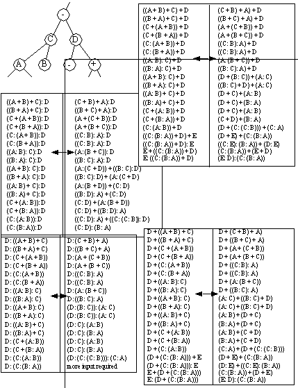
Figure 8.9 Transformation Tables for Moving Node A up CSG Trees (Read the tables as a form in the left hand column is equivalent to that in the right hand column) When attempting to eliminate redundant primitives in a CSG tree, a Null Object Detection (NOD) algorithm may be used. (Please note that the assumption with this technique is that unused and redundant primitives are undesirable). The algorithm attempts to locate primitives that cancel each other out. Tilove [1984] describes his use of Boolean algebra properties to design algorithms to detect null objects. This is done through a set of five algorithms he presents, which look for positive, and negative redundancy by direct examination of the tree. Tilove also describes previous algorithms that were not based on CSG methods and required greater access to computational resources. As an aside, he also states that the NOD algorithm can be used as the basis for Same Object Detection (SOD). This is useful when trying to ascertain if two objects are indeed similar. 8.7.2 Boolean Algebra Manipulation of Data StructuresAs discussed before, we may store and manipulate the Boolean expressions. The data structures discussed in the previous section did not discuss the addition of Boolean algebra whereas this section will. A set of routines were written to apply the rules of Boolean algebra to manipulate the equations. The fundamental operations are given in Figure 8.10 Fundamental Boolean Operations. All but Identity and Duality have been implemented in the software. 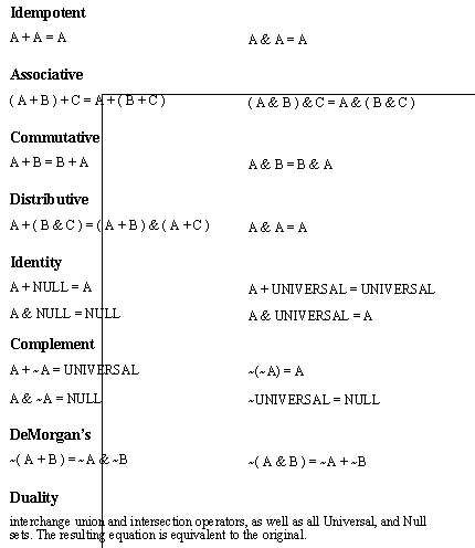
Figure 8.10 Fundamental Boolean Operations These operations are set up so that they may be applied in a parametric manner (see Mendelson [1989], for more information on Boolean algebra). In other words, there may be a term ‘(+ A B C)’. The law of Commutivity says that the expression may have up to six (3! = 3*2*1) forms; ‘(+ A B C)’, ‘(+ A C B)’, ‘(+ C B A)’, ‘(+ B A C)’, ‘(+ B C A)’, and ‘(+ C A B)’. Therefore the law of Commutivity can be applied to some term, a finite number of ways. By expressing the manipulation in this manner, the method of manipulating equations becomes similar to methods used in tree searches (i.e., the operator is a simple finite description). This becomes the first step to deriving an exhaustive method for equation manipulation. The list below shows all of the operations used, and gives examples of how they are applied. In this expression there are n=6 terms, and therefore there are (n-1)(n-2)...(1) possible combinations for application. Of this there are only 3 that can be successfully performed in the example equation. This is between the first three ‘A’s. The last ‘A’ is considered different because it has a ‘;e’ appended.There are n=4 possible candidates for this operation of which two are bracketed, and one of those two has the same sign. The ‘( & E F )’ term can be ‘popped’ because it has the same operation as the parent term.For this operation it was chosen to allow each possible commutation (see commutative operator). This gives a total n!(n!) possible permutations that are acceptable for this operation.There are n! possible acceptable permutations for this operation. In simple words this operation only shuffles the order of the terms in the equation.Again there is only one possible permutation possible here. If a double negative exists, then it is replaced with the doubly negated termThere are n=3 possible permutations possible, but only one of these three has the double negative required for this operation to be successful.Possible result,( ~ ( & ( ~ A ) ( ~ B ) C D;x;y ) Obviously these methods can be used to simplify, or complicate an expression. In the next section the application of these operators will be addressed. 8.7.3 Automatically Generating Boolean EquationsThe operators described in the last section were described using permutation parameters. To manipulate the equation the user must specify the i) operation of interest, ii) simplification or complication, and iii) the permutation of the operation desired. As these are specified, the equation may be changed. If they are applied blindly using an exhaustive search, the possible variations are enormous (actually infinite). A directed searches is one possible method for reducing the search space. Exhaustive methods are the most dependable methods for finding any given term. But this reliability comes with a high cost on efficiency. In the case of simplifying the equation to a disjunctive normal form, the method is slow, but very effective. To reduce an equation to its simplest form, we need only to apply the operators discussed in the previous section, until all possible alternatives have been exhausted. It was found that to start with the most nested terms resulted in a more direct solution. The basic algorithm is described below. 1. Get a list of all terms in the equation, in hierarchical order. That is the last item on the list of terms, would be one of the first operations performed mathematically. 2. Pick the last term on the list, and begin testing to see if any simplifying operators can be applied. If no operators are fired, then remove the last item from the list, and begin step 2 again. If the list is empty, the equation is simplified, so quit. 3. If an operator was fired successfully, then return to 1. For the software written, this Exhaustive Simplify operation takes a few seconds for an example with between 10 and 20 terms. If the code were optimized, the simplification would take less than a second. Exhaustive Simplification has a goal, therefore making the algorithm easy. Exhaustive complication has no goals, but it continually expands an infinite tree systematically. More importantly, when simplifying, there is only one term at all times. But, when complicating, each new term must now be kept. This is obviously not very practical, but useful to note. The exhaustive equation manipulations focus on complicating, and simplifying expressions. But, if we merely want to generate alternatives, we may use a more interesting algorithm. A Random Walk through equation space may be of use for obtaining novel equation forms. In this case a term in the equation is chosen at random, and one operator is randomly selected, and the operators permutation is also randomly selected. This would allow the equation to be made simpler in some cases, more complex in others, and change the topology of the equation. While this is sort of a blind technique, it does lay the groundwork for a more complex heuristic search. At present the simplification technique is the only one used, but the future potential for this method is excellent. The advanced use of equation manipulation will be discussed more later with reference to Meta-knowledge. While the equation forms presented before concentrate on high level representation of the product, they do not consider representation of set properties. To allow set properties to accompany the equations, a symbolic form of representation has been chosen. Each symbol in the equation has a list of symbols associated with it. This allows a set of arbitrary properties to be associated with each set. For example, if we have a Boolean expression ‘( * A ( ~ B ) )’, it is possible for ‘B’ to have a list of properties such as, B.height_max_tolerance = +0.02 The reason for this representation is that it is not necessary to be more specific for this method. The reader will notice in the next chapter that the CAPP planning rules are made to use arbitrary symbols. This allows more freedom in the CAD system, where geometry is represented because it is essential, but the other properties are often ignored because they are a nuisance for the CAD software designer. The set ‘B’ above can be used to illustrate some common problems related to tightly specified data components. The form of ‘B’ is a cylinder. When this is interpreted in the solid modeler, the location of the origin for the primitive is critical. But, various solid modelers set the origin either at the centre of one end or at the centre of mass. Obviously this would lead to the definition of two different geometries. The data structure to store symbol lists is given in Figure 8.11 Set Data Structure (With Example). In the diagram there are two lists, and a pointer into the lists. There are two separate types of lists stored. The first list is for all sets (not including members). The second list is specifically for the set members (also called properties). In the diagram there is a pointer to the set list. This serves as a reference to the position in the set list. The ‘Term List’ is used specifically for lists of objects (and is similar to the ‘Term List’ used for storing equations, and it uses the same C++ class). The ‘pointer’ field refers to symbols containing the name of the set. The ‘type’ field is filled in to indicate that it is a set pointer, but this is only useful for checking data integrity. Obviously the ‘point to next’ field is used for linking the lists. The list of symbols are treated in a similar manner. The symbol list is used to store the set names and the symbol names. Pointers are also used for the set names. These pointers refer back to the term list, so as to give the list of symbols. The type field is used to differentiate between numeric and symbolic properties. This reason for this becomes apparent when trying to compare fields, and field values. Numeric values must be treated differently than character strings. 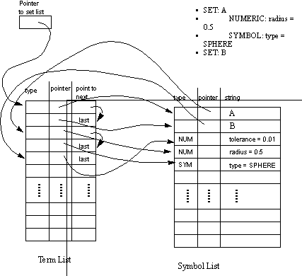
Figure 8.11 Set Data Structure (With Example) A set of functions has been developed to manipulate the data structures. Some of these functions are, find a reference to a set/property, The basic theory behind solid modelling was reviewed, including the fundamental operators. Of particular interest was the Assembly operator. While it was shown that there are currently no satisfactory techniques for assembly modelling, it was made clear that techniques are evolving. The product representation was presented, including a basic structure, and details necessary for a computer implementation. The representation includes data structures capable of storing and manipulating Boolean equations. These equations also refer to sets of properties. The final data structure was selected in such a way that the method of representation (r-sets/s-set/CNRG/etc.) did not have to be chosen. This can be said because at no point is the data structure interpreted physically, thereby forcing a selection of representation. There are a number of highlights from various sections of this chapter. The attributes of sets, such as tolerances, have been left undefined to allow for the greatest flexibility in future use. (Only a few very fundamental properties have been defined, such as position). The computer was able to generate a graphical representation of the part based upon the part file. This indicates that the method is at least sufficient for geometrical representation. The nested Boolean form has been used to eliminate ambiguities in operator scope. Properties may be appended to sets and primitives. This allows reuse of basic parts as would be desired in an Engineering design environment. Most of the common Boolean algebra axioms are included in the equation manipulation subroutines. |