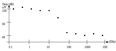
FREQUENCY RESPONSE FUNCTIONSIn many cases the behavior of a system must be determined experiementally. One common method is to excite the system with a range of input frequencies, measure the output response, and plot the gain and phase. This is the experimental equivalent of the Bode plot, called the Frequency Response Functions (FRF). Practically this means that you apply an impulse function (literally a hammer for some systems). The response is measures as a power magnitude over a range of frequencies, using a spectrum analyzer. Or, an input can be set to different frequencies and the output response measured, multiple frequencies are used to contruct a graph, like the one shown in Figure 10.24 Example FRF. 
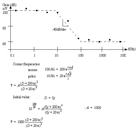
This can be converted to a Bode plot, then transfer function by doing a straight line fit to the function. When the graph is drawn using experimental values there is some need to allow for points that are off the straight line. In other words, fit the curve using a good educated guess. Then using the form of the graph work backwards to construct a transfer function. 
|