When modeling translational systems it is common to break the system into parts. These parts are then described with Free Body Diagrams (FBDs). Common components that must be considered when constructing FBDs are listed below, and are discussed in following sections.
• dampers and drag - resist motion
• friction - opposes relative motion between bodies in contact
• cables and pulleys - redirect forces
• contact points/joints - transmit forces through up to 3 degrees of freedom
• inertia - opposes acceleration and deceleration
• gravity and other fields - apply non-contact forces
Free Body Diagrams (FBDs) allow us to reduce a complex mechanical system into smaller, more manageable pieces. The forces applied to the FBD can then be summed to provide an equation for the piece. These equations can then be used later to do an analysis of system behavior. These are required elements for any engineering problem involving rigid bodies.
An example of FBD construction is shown in Figure 2.3 Free body diagram example. In this case there is a mass sitting atop a spring. An FBD can be drawn for the mass. In total there are two obvious forces applied to the mass, gravity pulling the mass downward, and a spring pushing the mass upwards. The FBD for the spring has two forces applied at either end. Notice that the spring force, FR1, acting on the mass, and on the spring have an equal magnitude, but opposite direction.

Figure 2.3 Free body diagram example
In a static system the sum of forces is zero and nothing is in motion. In a dynamic system the sum of forces is not zero and the masses accelerate. The resulting imbalance in forces acts on the mass causing it to accelerate. For the purposes of calculation we create a virtual reaction force, called the inertial force. This force is also known as D’Alembert’s (pronounced as daa-lamb-bears) force. It can be included in calculations in one of two ways. The first is to add the inertial force to the FBD and then add it into the sum of forces, which will equal zero. The second method is known as D’Alembert’s equation where all of the forces are summed and set equal to the inertial force, as shown in Figure 2.4 D’Alembert’s and Newton’s equations. The acceleration is proportional to the inertial force and inversely proportional to the mass.

Figure 2.4 D’Alembert’s and Newton’s equations
An application of Newton’s equation to FBDs can be seen in Figure 2.5 Free body diagram and inertial forces. In the first case an inertial force is added to the FBD. This force should be in an opposite direction (left here) to the positive direction of the mass (right). When the sum of forces equation is used then the force is added in as a normal force component. In the second case Newton’s equation is used so the force is left off the FBD, but added to the final equation. In this case the sign of the inertial force is positive if the assumed positive direction of the mass matches the positive direction for the summation.
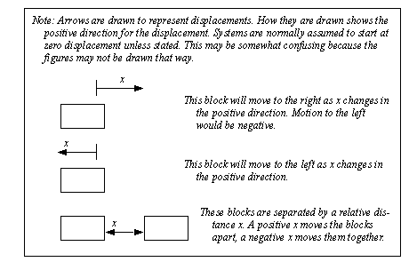
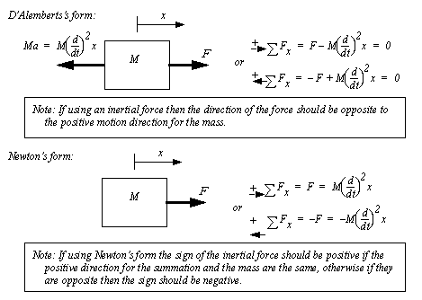
Figure 2.5 Free body diagram and inertial forces
An example of the application of Newton’s equation is shown in Figure 2.6 Example: Acceleration calculation. In this example there are two unbalanced forces applied to a mass. These forces are summed and set equal to the inertial force. Solving the resulting equation results in acceleration values in the ’x’ and ’y’ directions. In this example the forces and calculations are done in vector form for convenience and brevity.
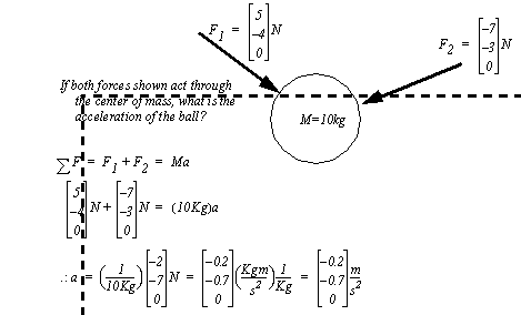
Figure 2.6 Example: Acceleration calculation
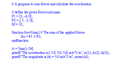
Figure 2.7 Example: A Scilab calculation
Gravity is a weak force of attraction between masses. In our situation we are in the proximity of a large mass (the earth) which produces a large force of attraction. When analyzing forces acting on rigid bodies we add this force to our FBDs. The magnitude of the force is proportional to the mass of the object, with a direction toward the center of the earth (down).
The relationship between mass and force is clear in the metric system with mass having the units Kilograms (kg), and force the units Newtons (N). The relationship between these is the gravitational constant 9.81N/kg, which will vary slightly over the surface of the earth. The Imperial units for force and mass are both the pound (lb.) which often causes confusion. To reduce this confusion the unit for force is normally modified to be, lbf.
An example calculation including gravitational acceleration is shown in Figure 2.8 Example: Gravity vector calculations. The 5kg mass is pulled by two forces, gravity and the arbitrary force ’F’. These forces are described in vector form, with the positive ’z’ axis pointing upwards. To find the equations of motion the forces are summed. To eliminate the second derivative on the inertia term the equation is integrated twice. The result is a set of three vector equations that describe the x, y and z components of the motion. Notice that the units have been carried through these calculations.
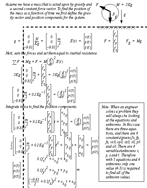
Figure 2.8 Example: Gravity vector calculations
Like gravity, magnetic and electrostatic fields can also apply forces to objects. Magnetic forces are commonly found in motors and other electrical actuators. Electrostatic forces are less common, but may need to be considered for highly charged systems.
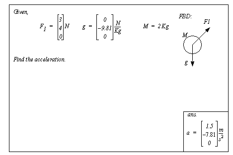
Figure 2.9 Drill Problem: Find the acceleration of the FBD
Springs are typically constructed with elastic materials such as metals and plastics, that will provide an opposing force when deformed. The properties of the spring are determined by the Young’s modulus (E) of the material and the geometry of the spring. A primitive spring is shown in Figure 2.10 A solid member as a spring. In this case the spring is a solid member. The relationship between force and displacement is determined by the basic mechanics of materials relationship. In practice springs are more complex, but the parameters (E, A and L) are combined into a more convenient form. This form is known as Hooke’s Law.

Figure 2.10 A solid member as a spring
Hooke’s law does have some limitations that engineers must consider. The basic equation is linear, but as a spring is deformed the material approaches plastic deformation, and the modulus of elasticity will change. In addition the geometry of the object changes, also changing the effective stiffness. Springs are normally assumed to be massless. This allows the inertial effects to be ignored, such as a force propagation delay. In applications with fast rates of change the spring mass may become significant, and they will no longer act as an ideal device.
The cases for tension and compression are shown in Figure 2.11 Sign conventions for spring forces and displacements. In the case of compression the spring length has been made shorter than its’ normal length. This requires that a compression force be applied. For tension, both the displacement from neutral and the required force reverse direction. It is advisable when solving problems to assume a spring is either in tension or compression, and then select the displacement and force directions accordingly.
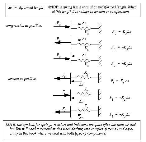
Figure 2.11 Sign conventions for spring forces and displacements
Previous examples have shown springs with displacements at one end only. In Figure 2.12 Examples of forces when both sides of a spring can move, springs are shown that have movement at both ends. In these cases the sign of the force applied to the spring is selected with reference to the assumed compression or tension. The primary difference is that care is required to correctly construct the expressions for the tension or compression forces. In all cases the forces on the springs must be assumed and drawn as either tensile or compressive. In the first example the displacement and forces are tensile. The displacement at the left is tensile, so it will be positive, but on the right hand side the displacement is compressive so it is negative. In the second example the force and both displacements are shown as tensile, so the terms are both positive. In the third example the force is shown as compressive, while the displacements are both shown as tensile, so both terms are negative.
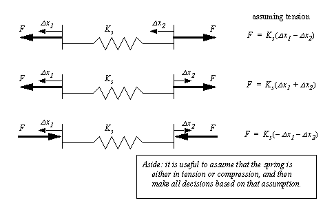
Figure 2.12 Examples of forces when both sides of a spring can move
The example in Figure 2.13 Drawing FBDs with interconnecting springs shows two masses separated by a spring. In the first example the spring is assumed to be in tension. When x1 becomes positive it will put the spring in compression, so it is made negative, however a positive x2 will put the spring in tension, so it remains positive. In the second case the spring is assumed to be in compression and this time x2 will put it in tension so it is made negative.
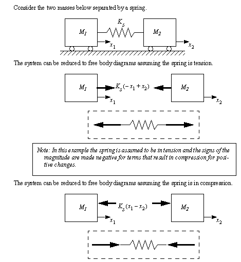
Figure 2.13 Drawing FBDs with interconnecting springs
Sometimes the true length of a spring is important, and the deformation alone is insufficient. In these cases the deformation can be defined as a deformed and undeformed length, as shown in Figure 2.14 Using the actual spring length.

Figure 2.14 Using the actual spring length
In addition to providing forces, springs may be used as energy storage devices. Figure 2.15 Energy stored in a spring shows the equation for energy stored in a spring.

Figure 2.15 Energy stored in a spring
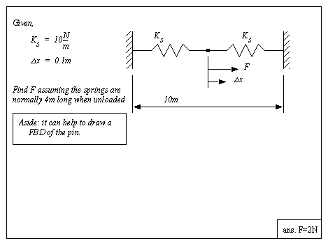
Figure 2.16 Drill problem: Deformation of a two spring system
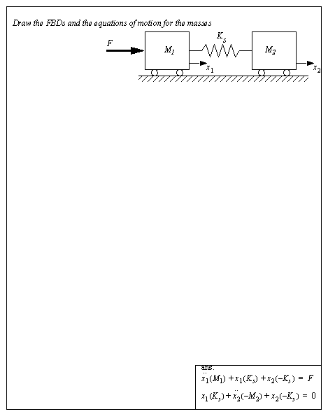
Figure 2.17 Drill problem: Draw the FBDs for the masses
A damper is a component that resists motion. The resistive force is relative to the rate of displacement. As mentioned before, springs store energy in a system but dampers dissipate energy. Dampers and springs are often used to compliment each other in designs.
Damping can occur naturally in a system, or can be added by design. The physical damper pictured in Figure 2.18 A physical damper uses a cylinder that contains a fluid. There is a moving rod and piston that can slide within the cylinder. As the piston moves, fluid is forced through a small orifice. When moved slowly the fluid moves easily, but when moved quickly the pressure required to force the fluid through the orifice rises. This rise in pressure results in a higher force of resistance. In ideal terms any motion would result in an opposing force. In reality there is also a break-away force that needs to be applied before motion begins. Other manufacturing variations could also lead to other small differences between dampers. Normally these cause negligible effects.

The basic equation for an ideal damper in compression is shown in Figure 2.19 An ideal damper. In this case the force and displacement are both compressive. The force is calculated by multiplying the damper coefficient by the velocity, or first derivative of position. Aside from the use of the first derivative of position, the analysis of dampers in systems is similar to that of springs.

Damping can also occur when there is relative motion between two objects. If the objects are lubricated with a viscous fluid (e.g., oil) then there will be a damping effect. In the example in Figure 2.20 Viscous damping between two bodies with relative motion two objects are shown with viscous friction (damping) between them. When the system is broken into free body diagrams the forces are shown to be a function of the relative velocities between the blocks.
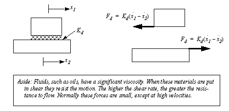
Figure 2.20 Viscous damping between two bodies with relative motion
A damping force is proportional to the first derivative of position (velocity). Aerodynamic drag is proportional to the velocity squared. The equation for drag is shown in Figure 2.21 Aerodynamic drag in vector and scalar forms. The drag force increases as the square of velocity. Normally, the magnitude of the drag force coefficient ’D’ is approximated theoretically and/or measured experimentally. The drag coefficient is a function of material type, surface properties, object size and object geometry.

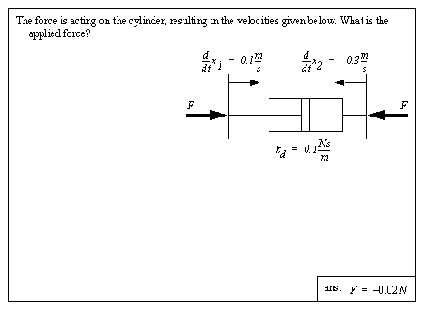
Figure 2.22 Drill problem: Find the required forces on the damper
Cables are useful when transmitting tensile forces or displacements. The centerline of the cable becomes the centerline for the force. And, if the force becomes compressive, the cable becomes limp, and will not transmit force. A cable by itself can be represented as a force vector. When used in combination with pulleys, a cable can redirect a force vector or multiply a force.
Typically we assume that a pulley is massless and frictionless (in the rotation chapter we will assume they are not). If this is the case then the tension in the cable on both sides of the pulley are equal, as shown in Figure 2.23 Tension in a cable over a massless frictionless pulley.

Figure 2.23 Tension in a cable over a massless frictionless pulley
If we have a pulley that is fixed and cannot rotate, the cable must slide over the surface of the pulley. In this case we can use the coefficient of friction to determine the relative ratio of forces between the sides of the pulley, as shown in Figure 2.24 Friction of a belt over a fixed drum.

Figure 2.24 Friction of a belt over a fixed drum
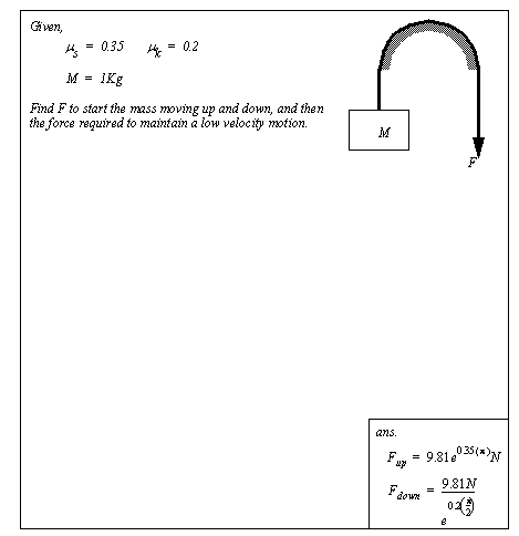
Figure 2.25 Drill problem: Friction forces for belts on drums
Although the discussion in this section has focused on cables and pulleys, the theory also applies to belts over drums.
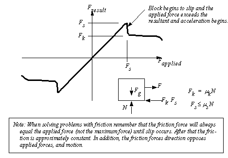
Viscous friction was discussed before, where a lubricant would provide a damping effect between two moving objects. In cases where there is no lubricant, and the touching surfaces are dry, dry coulomb friction may result. In this case the surfaces will stick in place until a maximum force is overcome. After that the object will begin to slide and a constant friction force will result.
Figure 2.26 Dry friction shows the classic model for (dry Coulomb) friction. The force on the horizontal axis is the force applied to the friction surfaces while the vertical axis is the resulting friction force. Beneath the slip force the object will stay in place. When the slip force is exceeded the object will begin to move, and the resulting kinetic friction force will be relatively constant. (Note: If the object begins to travel much faster then the kinetic friction force will decrease.) It is common to forget that friction forces are bidirectional, but it always opposes the applied force or motion. The friction force is a function of the coefficient of friction and the normal force across the contact surfaces. The coefficient of friction is a function of the materials, surface texture and surface shape.
Many systems use kinetic friction to dissipate energy from a system as heat, sound and vibration.
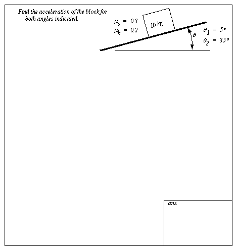
Figure 2.27 Drill problem: Find the accelerations
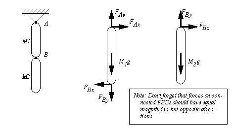
A system is built by connecting components together. These connections can be rigid or moving. In solid connections all forces and moments are transmitted and the two pieces act as a single rigid body. In moving connections there is at least one degree of freedom. If we limit this to translation only, there are up to three degrees of freedom, x, y and z. In any direction there is a degree of freedom, a force or moment cannot be transmitted.
When constructing FBDs for a system we must break all of the components into individual rigid bodies. Where the mechanism has been broken the contact forces must be added to both of the separated pieces. Consider the example in Figure 2.28 FBDs for systems with connected members. At joint A the forces are written as two components in the x and y directions. For joint B the force components with equal magnitudes but opposite directions are added to both FBDs.
