PHASORS FOR STEADY-STATE ANALYSIS
When considering the differential operator we can think of it as a complex number, as in Figure 9.1 Transient and steady-state parts of the differential operator. The real component of the number corresponds to the natural decay (e-to-the-t) of the system. But, the complex part corresponds to the oscillations of the system. In other words the real part of the number will represent the transient effects of the system, while the complex part will represent the sinusoidal steady-state. Therefore to do a steady-state sinusoidal analysis we can replace the ’D’ operator with 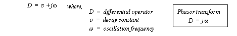
Figure 9.1 Transient and steady-state parts of the differential operator An example of the phasor transform is given in Figure 9.2 A phasor transform example. We start with a transfer function for a mass-spring-damper system. In this example numerical values are assumed to put the equation in a numerical form. The differential operator is replaced with jω, and the equation is simplified to a complex number in the denominator. This equation then described the overall response of the system to an input based upon the frequency of the input. A generic form of sinusoidal input for the system is defined, and also converted to phasor (complex) form. (Note: the frequency of the input does not show up in the complex form of the input, but it will be used later.) The steady state response of the system is then obtained by multiplying the transfer function by the input, to obtain the output. 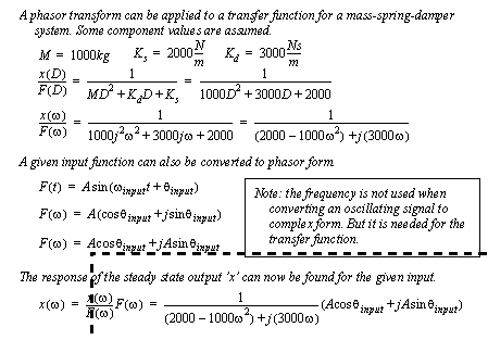
Figure 9.2 A phasor transform example To continue the example in Figure 9.2 A phasor transform example values for the sinusoidal input force are assumed. After this the method only requires the simplification of the complex expression. In particular having a complex denominator makes analysis difficult and is undesirable. To simplify this expression it is multiplied by the complex conjugate. After this, the expression is quickly reduced to a simple complex number. The complex number is then converted to polar form, and then finally back into a function of time. 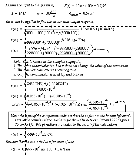
Figure 9.3 A phasor transform example (cont’d) 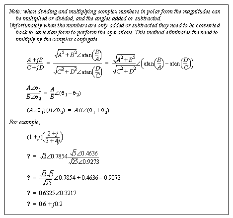
Figure 9.4 Calculations in polar notation The cartesian form of complex numbers seen in the last section are well suited to operations where complex numbers are added and subtracted. But, when complex numbers are to be multiplied and divided these become tedious and bulky. The polar form for complex numbers simplifies many calculations. The previous example started in Figure 9.2 A phasor transform example is redone using polar notation in Figure 9.5 Correcting quadrants for calculated angles. In this example the input is directly converted to polar form, without the need for calculation. The input frequency is substituted into the transfer function and it is then converted to polar form. After this the output is found by multiplying the transfer function by the input. The calculations for magnitudes involve simple multiplications. The angles are simply added. After this the polar form of the result is converted directly back to a function of time. 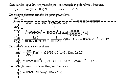
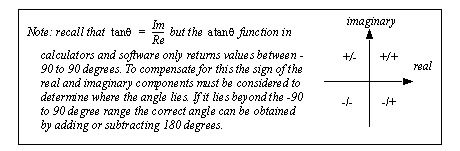
Figure 9.5 Correcting quadrants for calculated angles Consider the circuit analysis example in Figure 9.6 Phasor analysis of a circuit. In this example the component values are converted to their impedances, and the input voltage is converted to phasor form. (Note: this is a useful point to convert all magnitudes to powers of 10.) After this the three output impedances are combined to a single impedance. In this case the calculations were simpler in the cartesian form. 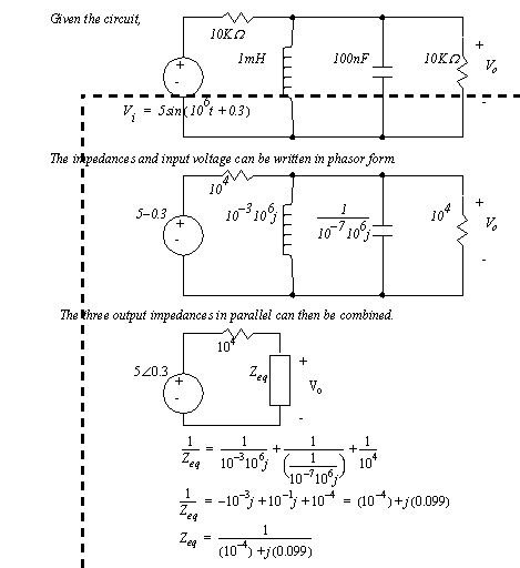
Figure 9.6 Phasor analysis of a circuit The analysis continues in Figure 9.7 Phasor analysis of a circuit (cont’d) as the output is found using a voltage divider. In this case a combination of cartesian and polar forms are used to simplify the calculations. The final result is then converted back from phasor form to a function of time. 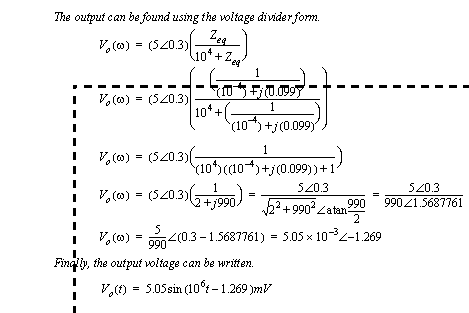
Figure 9.7 Phasor analysis of a circuit (cont’d) Phasor analysis is applicable to systems that are linear. This means that the principle of superposition applies. Therefore, if an input signal has more than one frequency component then the system can be analyzed for each component, and then the results simply added. The example considered in Figure 9.2 A phasor transform example is extended in Figure 9.8 A example for a signal with multiple frequency components (based on the example in Figure 9.2). In this example the input has a static component, as well as frequencies at 0.5 and 20 rad/s. The transfer function is analyzed for each of these frequencies components. The output components are found by multiplying the inputs by the response at the corresponding frequency. The results are then converted back to functions of time, and added together. 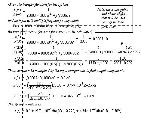
Figure 9.8 A example for a signal with multiple frequency components (based on the example in Figure 9.2 A phasor transform example) |
 , this is the phasor transform.