DESIGN CASEThe classic mass-spring-damper system is shown in Figure 6.19 Example: A transfer function for a mechanical system. In this example the forces are summed to provide an equation. The differential operator is replaced, and the equation is manipulated into transfer function form. The transfer function is given in two different forms because the system is reversible and the output could be either ’F’ or ’x’. 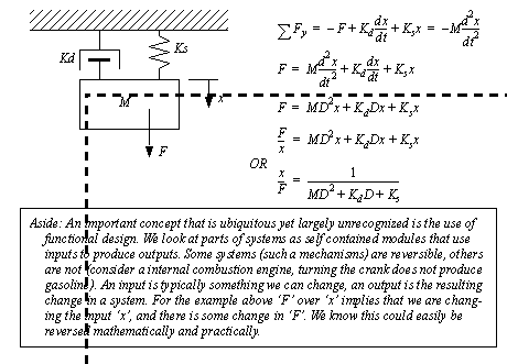
Figure 6.19 Example: A transfer function for a mechanical system 
Mass-spring-damper systems are often used when doing vibration analysis and design work. The first stage of such analysis involves finding the actual displacement for a given displacement or force. A system experiencing a sinusoidal oscillating force is given in Figure 6.20 Example: Explicit analysis of a mechanical system. Numerical values are substituted and the homogeneous solution to the equation is found. 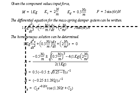
Figure 6.20 Example: Explicit analysis of a mechanical system The solution continues in Figure 6.21 Example: Explicit analysis of a mechanical system (continued) where the particular solution is found and put in phase shift form. 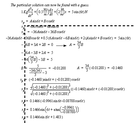
Figure 6.21 Example: Explicit analysis of a mechanical system (continued) The system is assumed to be at rest initially, and this is used to find the constants in the homogeneous solution in Figure 6.22 Example: Explicit analysis of a mechanical system (continued). Finally the displacement of the mass is used to find the force exerted through the spring on the ground. In this case there are two force frequency components at 1.392rad/s and 6rad/s. The steady-state force at 6rad/s will have a magnitude of .2932N. The transient effects have a time constant of 4 seconds (1/0.25), and should be negligible within a few seconds of starting the machine. 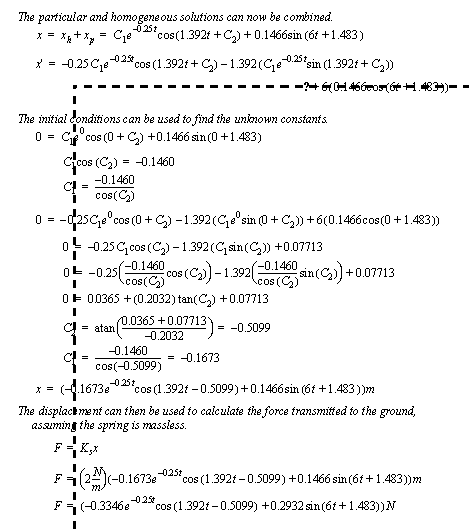
Figure 6.22 Example: Explicit analysis of a mechanical system (continued) A decision has been made to reduce the vibration magnitude transmitted to the ground to 0.1N. This can be done by adding a mass-spring isolator, as shown in Figure 6.23 Example: Vibration isolation system. In the figure the bottom mass-spring-damper combination is the original system. The mass and spring above have been added to reduce the vibration that will reach the ground. Values must be selected for the mass and spring. The design begins by developing the differential equations for both masses. 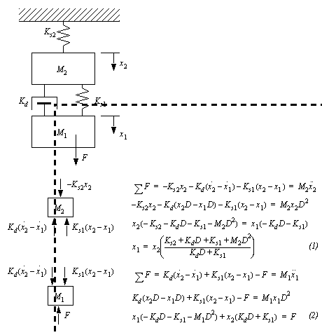
Figure 6.23 Example: Vibration isolation system For the design we are only interested in the upper spring, as it determines the force on the ground. An input-output equation for that spring is developed in Figure 6.24 Example: Developing an input output equation. The given values for the mass-spring-damper system are used. In addition a value for the upper mass is selected. This is arbitrarily chosen to be the same as the lower mass. This choice may need to be changed later if the resulting spring constant is not practical. 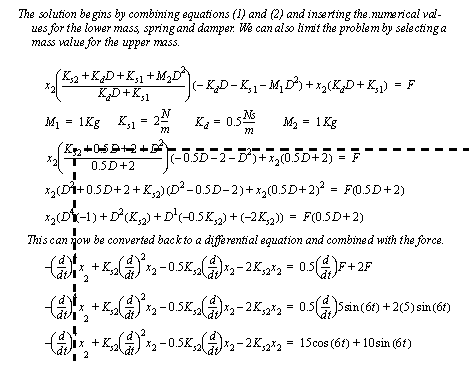
Figure 6.24 Example: Developing an input output equation This particular solution of the differential equation will yield the steady-state displacement of the upper mass. This can then be used to find the needed spring coefficient. 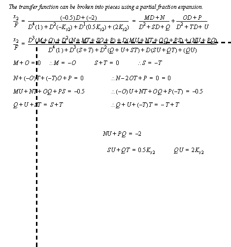
Figure 6.25 Example: Developing an input output equation 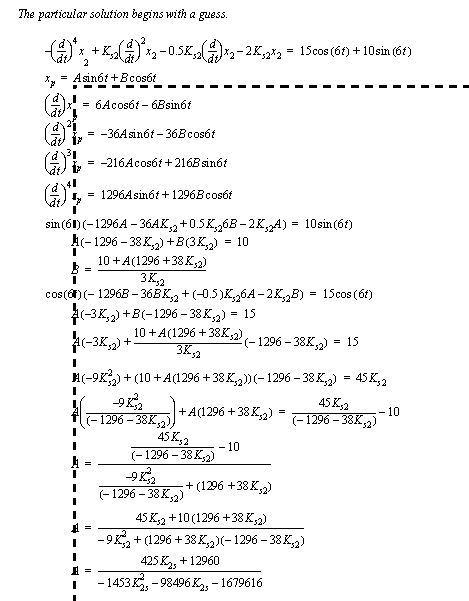
Figure 6.26 Example: Finding the particular solution 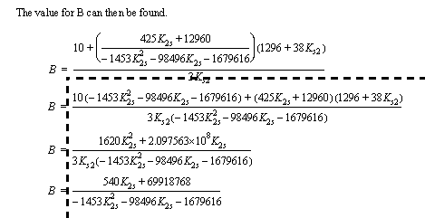
Figure 6.27 Example: Finding the particular solution (cont’d) Finally the magnitude of the particular solution is calculated and set to the desired amplitude of 0.1N. This is then used to calculate the spring coefficient. 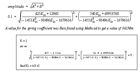
|