APPENDICES34.6.1 Appendix A - Sample SystemThe example system in Figure 34.2 System Architecture is to control a cart with a hanging pendulum. The cart is driven by a motor. The motor has an attached encoder to measure the motor position. As the cart moves the mass underneath may sway. The position of the hanging mass is measured with a potentiometer. 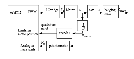
Figure 34.2 System Architecture A block diagram for the system is shown in Figure 34.3 System Block Diagram. A motion generator is used to generate a smooth path for the mass. There are two feedback control loops. The first loop adjusts the motor for general positioning of the system. The inner loop adjusts the output to reduce sway of the cart. The two control signals are added to produce a command signal the drives the load to the final position and then reduces vibrations. 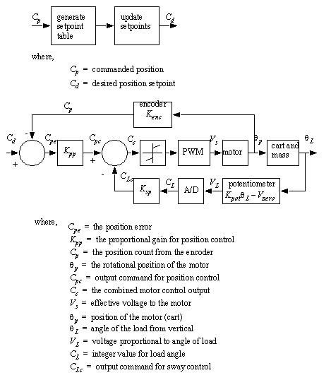
Figure 34.3 System Block Diagram 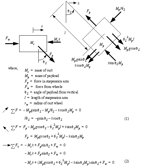
Figure 34.4 FBDs for the suspended mass and the compensator 
Figure 34.5 Adding the differential equation for the motor 
Figure 34.6 State equations for the system A Scilab program that simulates the given system is given in Figure 34.7 A Scilab program to simulate the swaying mass on the crane. 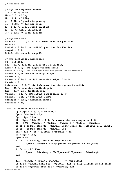
Figure 34.7 A Scilab program to simulate the swaying mass on the crane 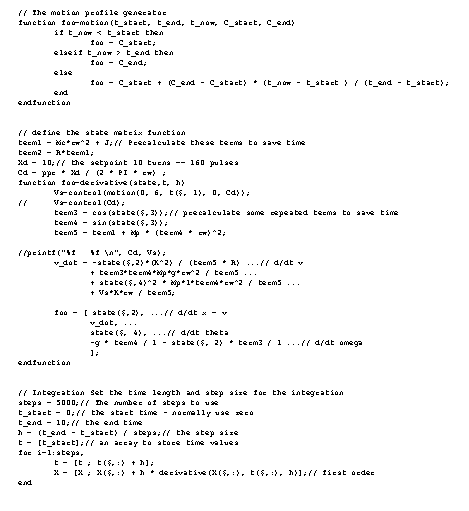
Figure 34.8 A Scilab program to simulate the swaying mass on the crane 
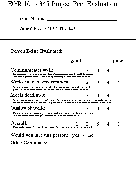
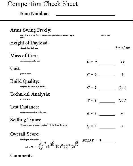
Figure 34.9 A Scilab program to simulate the swaying mass on the crane 34.6.2 Appendix B - EGR 345/101 ContractThe text below outlines the general form of a contract between students in EGR 101 and 345. This contract has been entered into this date by the parties of the first part Joe Junior, Pete Zaa, Anne Nyther and Robert Sochs, to be referred to as ’345 students’, with Virve Meurte, to be referred to as ’101 student(s)’. 1. The 101 student is to participate in the design and construction of a cart as outlined below. The 345 students are to prepare a design and construct a multicomponent system that uses the cart as described below. The result must be a fully functional systems that meets the published design objectives. 2. The 345 students are expected to prepare a functional design for an anti-sway system for a crane. This design will include a cart that is designed in coordination with the 101 student. The 345 students will be required to do all calculation including system dynamics and strength of materials. The 101 student will be responsible for all other design details related to the cart including the geometry, mass, budget bill of materials and construction. This design will be documented fully by the 101 student using accepted CAD practices and ProE. The design work will result in the submission of a Formal Proposal, as shown on the Schedule of Actions. 3. Dr. Jack and/or Farris will comment on the Formal Proposal. Based upon these comments the 101 and 345 students will revise the design and agree upon a design for the cart. This will be labelled Cart Build Approval. This will be signed by all parties and submitted to Dr. Farris by the Scheduled date. 4. The cart will be build according to the Cart Build Approval before the date specified on the Schedule of Actions. At the end of this period the design must be fully documented in ProE and be ready for inclusion in the Design Report Draft. 5. Both the 101 and 345 students will participate in the first tests to verify the operation of the system and develop a First List of Deficiencies. This list will be finalized and signed, according to the date on the Schedule of Actions. The First List of Deficiencies will include a list of remedies to be performed by the 101 and 345 students. 6. The 345 students will prepare the Design Report Draft using the ProE drawing submitted by the 101 student. They are responsible for submitting the report by the date in the Schedule of Actions. 7. Both the 101 and 345 students will participate in the final tests to verify the operation of the system and develop a Final List of Deficiencies. This list will be finalized and signed, according to the date on the Schedule of Actions. The Final List of Deficiencies will include a list of remedies to be performed by the 101 and 345 students. Any changes made to the design must be updated and submitted to the 345 students for inclusion in the Design Report. 8. Both the 101 and 345 students will participate in the Competition listed in the Schedule of Actions. 9. The 345 students are to submit the final report with all necessary changes by the date listed in the Schedule of Actions. 10. The 101 student is expected to produce a cart that is built to professional standards. All drawings are expected to observe professional standards. When communicating drawings, generally accessible files formats should be used. 11. The 345 students are to, at all times, maintain a functional design concept. They must ensure that this will lead to a system that functions within the rules of the competition. 12. In the event of a dispute, 101 and 345 students are expected to resolve any conflicts informally and mitigate any losses. In the event that one or both parties fundamentally breach the contract Dr. Farris and Dr. Jack will acts as arbiters. If this occurs, one or both of the parties will be penalized. This may involve actions as severe as receiving a failing grade in the project. Oct 15-24 - Cart designs are developed by 101 and 345 students resulting in submission of the Formal Proposal Oct 30, 2003 - Cart Build Approval submitted Nov 11 - Initial build completed Nov 12 - First test completed and First List of Deficiencies submitted Nov 15 - Design Report Draft submitted for review Nov 19 - Final test completed and Final List of Deficiencies submitted 34.6.3 Appendix C - Forms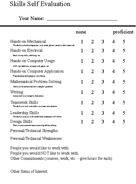

|