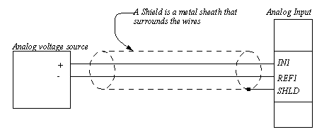
NOISE REDUCTIONSignals from sensors are often not in a form that can be directly input to a controller. In these cases it may be necessary to buy or build signal conditioners. Normally, a signal conditioner is an amplifier, but it may also include noise filters, and circuitry to convert from current to voltage. This section will discuss the electrical and electronic interfaces between sensors and controllers. Analog signal are prone to electrical noise problems. This is often caused by electromagnetic fields on the factory floor inducing currents in exposed conductors. Some of the techniques for dealing with electrical noise include; twisted pairs - the wires are twisted to reduce the noise induced by magnetic fields. shielding - shielding is used to reduce the effects of electromagnetic interference. single/double ended inputs - shared or isolated reference voltages (commons). When a signal is transmitted through a wire, it must return along another path. If the wires have an area between them the magnetic flux enclosed in the loop can induce current flow and voltages. If the wires are twisted, a few times per inch, then the amount of noise induced is reduced. This technique is common in signal wires and network cables. A shielded cable has a metal sheath, as shown in Figure 13.13 Cable Shielding. This sheath needs to be connected to the measuring device to allow induced currents to be passed to ground. This prevents electromagnetic waves to induce currents (and voltages) in the signal wires. 
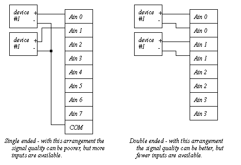
When connecting analog voltage sources to a controller the common, or 0V reference voltage, can be connected different ways, as shown in Figure 13.14 Single and Double Ended Inputs. The least expensive method uses one shared common for all analog signals, this is called single ended. The more accurate method is to use separate commons for each signal, this is called double ended. Most analog input cards allow a choice between one or the other. But, when double ended inputs are used the number of available inputs is halved. Most analog output cards are double ended. 
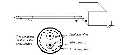
Figure 13.14 Single and Double Ended Inputs 13.4.1 ShieldingWhen a changing magnetic field cuts across a conductor, it will induce a current flow. The resistance in the circuits will convert this to a voltage. These unwanted voltages result in erroneous readings from sensors, and signal to outputs. Shielding will reduce the effects of the interference. When shielding and grounding are done properly, the effects of electrical noise will be negligible. Shielding is normally used for; all logical signals in noisy environments, high speed counters or high speed circuitry, and all analog signals. There are two major approaches to reducing noise; shielding and twisted pairs. Shielding involves encasing conductors and electrical equipment with metal. As a result electrical equipment is normally housed in metal cases. Wires are normally put in cables with a metal sheath surrounding both wires. The metal sheath may be a thin film, or a woven metal mesh. Shielded wires are connected at one end to "drain" the unwanted signals into the cases of the instruments. Figure 13.15 Shielding for a Thermocouple shows a thermocouple connected with a thermocouple. The cross section of the wire contains two insulated conductors. Both of the wires are covered with a metal foil, and final covering of insulation finishes the cable. The wires are connected to the thermocouple as expected, but the shield is only connected on the amplifier end to the case. The case is then connected to the shielding ground, shown here as three diagonal lines. 
Figure 13.15 Shielding for a Thermocouple A twisted pair is shown in Figure 13.16 A Twisted Pair. The two wires are twisted at regular intervals, effectively forming small loops. In this case the small loops reverse every twist, so any induced currents are cancel out for every two twists. 
When designing shielding, the following design points will reduce the effects of electromagnetic interference. • Avoid “noisy” equipment when possible. • Choose a metal cabinet that will shield the control electronics. • Use shielded cables and twisted pair wires. • Separate high current, and AC/DC wires from each other when possible. • Use current oriented methods such as sourcing and sinking for logical I/O. • Use high frequency filters to eliminate high frequency noise. • Use power line filters to eliminate noise from the power supply. 13.4.2 Grounding- ground voltages are based upon the natural voltage level in the physical ground (the earth under your feet). This will vary over a distance. Most buildings and electrical systems use a ground reference for the building. Between different points on the same building ground voltage levels may vary as much as a few hundred millivolts. This can lead to significant problems with voltage readings and system safety. - A signal can be floating, or connected to a ground - if floating a system normally has a self contained power source, or self reference such as a battery, strain gauge or thermocouple. These are usually read with double ended outputs. The potential for floating voltage levels can be minimized by connecting larger resistors (up to 100K) from the input to ground. - a grounded system uses a single common (ground) for all signals. These are normally connected to a single ended inputs. - the analog common can also be connected to the ground with a large resistor to drain off induced voltages. - cable shields or grounds are normally only connected at one side to prevent ground loops. |