INTRODUCTIONAn analog value is continuous, not discrete, as shown in Figure 13.1 Logical and Continuous Values. In the previous chapters, techniques were discussed for designing continuos control systems. In this chapter we will examine analog inputs and outputs so that we may design continuous control systems that use computers. 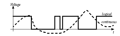
Figure 13.1 Logical and Continuous Values Typical analog inputs and outputs for computers are listed below. Actuators and sensors that can be used with analog inputs and outputs will be discussed in later chapters. A basic analog input is shown in Figure 13.2 Analog inputs. In this type of system a physical value is converted to a voltage, current or other value by a transducer. A signal conditioner converts the signal from the transducer to a voltage or current that is read by the analog input. 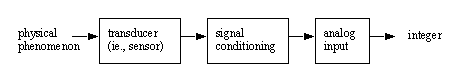
Analog to digital and digital to analog conversion uses integers within the computer. Integers limit the resolution of the numbers to a discrete, or quantized range. The effect of using integers is shown in Figure 13.3 Quantization error where the desired or actual analog value is continuous, but the possible integer values are quantified with a ’staircase’ set of values. Consider when a continuous analog voltage is being read, it must be quantized into an available integer value. Likewise, a desired analog output value is limited to available quantized values. In general the difference between the analog and quantized integer value is an error based upon the resolution of the analog I/O. 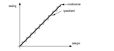
|