6.4.1 Angular Displacement
6.4.1.1 - Potentiometers
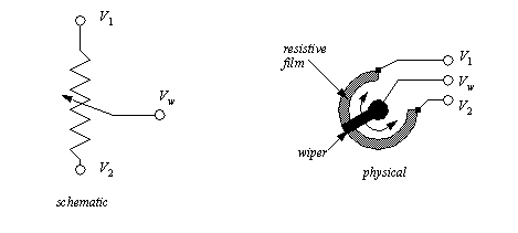
Potentiometers measure the angular position of a shaft using a variable resistor. A potentiometer is shown in Figure 6.15 A Potentiometer. The potentiometer is resistor, normally made with a thin film of resistive material. A wiper can be moved along the surface of the resistive film. As the wiper moves toward one end there will be a change in resistance proportional to the distance moved. If a voltage is applied across the resistor, the voltage at the wiper interpolate the voltages at the ends of the resistor.
Figure 6.15 A Potentiometer
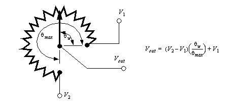
The potentiometer in Figure 6.16 A Potentiometer as a Voltage Divider is being used as a voltage divider. As the wiper rotates the output voltage will be proportional to the angle of rotation.
Figure 6.16 A Potentiometer as a Voltage Divider
Potentiometers are popular because they are inexpensive, and don’t require special signal conditioners. But, they have limited accuracy, normally in the range of 1% and they are subject to mechanical wear.
Potentiometers measure absolute position, and they are calibrated by rotating them in their mounting brackets, and then tightening them in place. The range of rotation is normally limited to less than 360 degrees or multiples of 360 degrees. Some potentiometers can rotate without limits, and the wiper will jump from one end of the resistor to the other.
Faults in potentiometers can be detected by designing the potentiometer to never reach the ends of the range of motion. If an output voltage from the potentiometer ever reaches either end of the range, then a problem has occurred, and the machine can be shut down. Two examples of problems that might cause this are wires that fall off, or the potentiometer rotates in its mounting.
6.4.2 Encoders
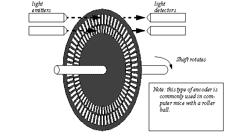
Encoders use rotating disks with optical windows, as shown in Figure 6.17 An Encoder Disk. The encoder contains an optical disk with fine windows etched into it. Light from emitters passes through the openings in the disk to detectors. As the encoder shaft is rotated, the light beams are broken. The encoder shown here is a quadrature encode, and it will be discussed later.
Figure 6.17 An Encoder Disk
There are two fundamental types of encoders; absolute and incremental. An absolute encoder will measure the position of the shaft for a single rotation. The same shaft angle will always produce the same reading. The output is normally a binary or grey code number. An incremental (or relative) encoder will output two pulses that can be used to determine displacement. Logic circuits or software is used to determine the direction of rotation, and count pulses to determine the displacement. The velocity can be determined by measuring the time between pulses.
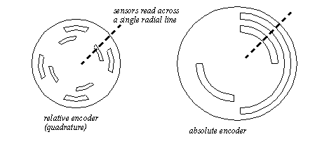
Encoder disks are shown in Figure 6.18 Encoder Disks. The absolute encoder has two rings, the outer ring is the most significant digit of the encoder, the inner ring is the least significant digit. The relative encoder has two rings, with one ring rotated a few degrees ahead of the other, but otherwise the same. Both rings detect position to a quarter of the disk. To add accuracy to the absolute encoder more rings must be added to the disk, and more emitters and detectors. To add accuracy to the relative encoder we only need to add more windows to the existing two rings. Typical encoders will have from 2 to thousands of windows per ring.
Figure 6.18 Encoder Disks
When using absolute encoders, the position during a single rotation is measured directly. If the encoder rotates multiple times then the total number of rotations must be counted separately.
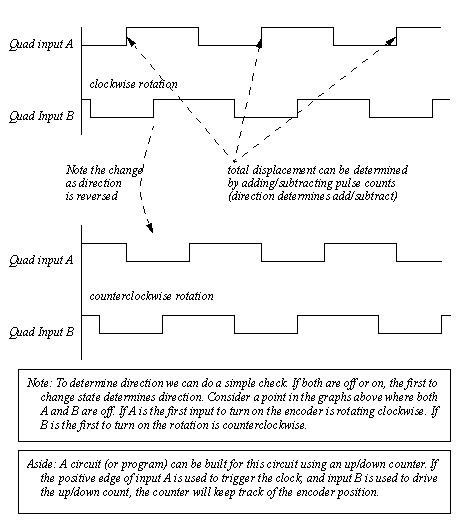
When using a relative encoder, the distance of rotation is determined by counting the pulses from one of the rings. If the encoder only rotates in one direction then a simple count of pulses from one ring will determine the total distance. If the encoder can rotate both directions a second ring must be used to determine when to subtract pulses. The quadrature scheme, using two rings, is shown in Figure 6.19 Quadrature Encoders. The signals are set up so that one is out of phase with the other. Notice that for different directions of rotation, input B either leads or lags A.
Figure 6.19 Quadrature Encoders
Interfaces for encoders are commonly available for PLCs and as purchased units. Newer PLCs will also allow two normal inputs to be used to decode encoder inputs.
Normally absolute and relative encoders require a calibration phase when a controller is turned on. This normally involves moving an axis until it reaches a logical sensor that marks the end of the range. The end of range is then used as the zero position. Machines using encoders, and other relative sensors, are noticeable in that they normally move to some extreme position before use.
6.4.2.1 - Tachometers
Tachometers measure the velocity of a rotating shaft. A common technique is to mount a magnet to a rotating shaft. When the magnetic moves past a stationary pick-up coil, current is induced. For each rotation of the shaft there is a pulse in the coil, as shown in Figure 6.20 A Magnetic Tachometer. When the time between the pulses is measured the period for one rotation can be found, and the frequency calculated. This technique often requires some signal conditioning circuitry.
Figure 6.20 A Magnetic Tachometer
Another common technique uses a simple permanent magnet DC generator (note: you can also use a small DC motor). The generator is hooked to the rotating shaft. The rotation of a shaft will induce a voltage proportional to the angular velocity. This technique will introduce some drag into the system, and is used where efficiency is not an issue.
Both of these techniques are common, and inexpensive.
