There are two basic counter types: count-up and count-down. When the input to a count-up counter goes true the accumulator value will increase by 1 (no matter how long the input is true.) If the accumulator value reaches the preset value the counter DN bit will be set. A count-down counter will decrease the accumulator value until the preset value is reached.
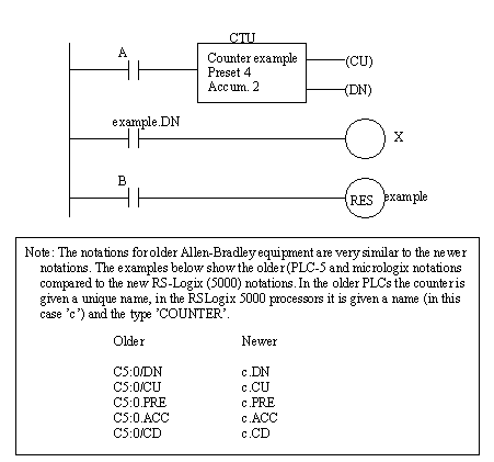
An Allen Bradley count-up (CTU) instruction is shown in Figure 8.1 An Allen Bradley Counter. The instruction requires memory in the PLC to store values and status, in this case is example. The preset value is 4 and the value in the accumulator is 2. If the input A were to go from false to true the value in the accumulator would increase to 3. If A were to go off, then on again the accumulator value would increase to 4, and the DN bit would go on. The count can continue above the preset value. If input B becomes true the value in the counter accumulator will become zero.

Figure 8.1 An Allen Bradley Counter
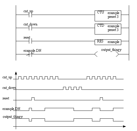
Count-down counters are very similar to count-up counters. And, they can actually both be used on the same counter memory location. Consider the example in Figure 8.1 A Counter Example, the example input cnt_up drives the count-up instruction for counter example. Input cnt_down drives the count-down instruction for the same counter location. The preset value for a counter is stored in memory location example so both the count-up and count-down instruction must have the same preset. Input reset will reset the counter.

The timing diagram in Figure 8.1 A Counter Example illustrates the operation of the counter. If we assume that the value in the accumulator starts at 0, then the positive edges on the cnt_up input will cause it to count up to 3 where it turns the counter example done bit on. It is then reset by input reset and the accumulator value goes to zero. Input cnt_up then pulses again and causes the accumulator value to increase again, until it reaches a maximum of 5. Input cnt_down then causes the accumulator value to decrease down below 3, and the counter turns off again. Input cnt_up then causes it to increase, but input reset resets the accumulator back to zero again, and the pulses continue until 3 is reached near the end.
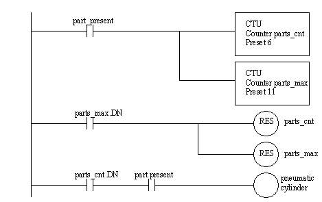
The program in Figure 8.1 A Counter Example is used to remove 5 out of every 10 parts from a conveyor with a pneumatic cylinder. When the part is detected both counters will increase their values by 1. When the sixth part arrives the first counter will then be done, thereby allowing the pneumatic cylinder to actuate for any part after the fifth. The second counter will continue until the eleventh part is detected and then both of the counters will be reset.
