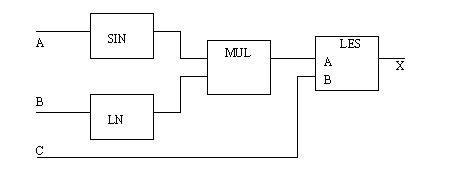
20. FUNCTION BLOCK PROGRAMMING• The basic construction of FBDs • The relationship between ST and FBDs • Constructing function blocks with structured text • To be able to write simple FBD programs Function Block Diagrams (FBDs) are another part of the IEC 61131-3 standard. The primary concept behind a FBD is data flow. In these types of programs the values flow from the inputs to the outputs, through function blocks. A sample FBD is shown in Figure 20.1 A Simple Calculation and Comparison Program. In this program the inputs A and B are used to calculate a value sin(A) * ln(B). The result of this calculation is compared to C. If the calculated value is less than C then the output X is turned on, otherwise it is turned off. Many readers will note the similarity of the program to block diagrams for control systems. 
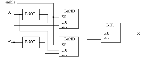
Figure 20.1 A Simple Calculation and Comparison Program It is possible to disable part of the FBDs using enables. These are available for each function block but may not be displayed. Figure 20.1 Using Enables in FBDs shows an XOR calculation. Both of the Boolean AND functions have the enable inputs connected to ’enable’. If ’enable’ is true, then the system works as expected and the output ’X’ is the exclusive OR of ’A’ and ’B’. However if ’enable’ is off then the BAND functions will not operate. In this case the ’enable’ input is not connected to the BOR function, but because it relies on the outputs from the BAND blocks, it will not function, and the output ’X’ will not be changed. 
Figure 20.1 Using Enables in FBDs A FBD program is constructed using function blocks that are connected together to define the data exchange. The connecting lines will have a data type that must be compatible on both ends. The inputs and outputs of function blocks can be inverted. This is normally shown with a small circle at the point where the line touches the function block, as shown in Figure 20.1 Inverting Inputs and Outputs on Function Blocks. (Note: this is NOT available for Allen Bradley RSLogix, so BNOT functions should be used instead.) 
Figure 20.1 Inverting Inputs and Outputs on Function Blocks The basic functions used in FBD programs are equivalent to the basic set used in Structured Text (ST) programs. Consider the basic addition function shown in Figure 20.1 A Simple Function Block. The ST function on the left adds A and B, and stores the result in O. The function block on the right is equivalent. By convention the inputs are on the left of the function blocks, and the outputs on the right. 
Figure 20.1 A Simple Function Block Some functions allow a variable number of arguments. In Figure 20.1 A Function with A Variable Argument List there is a third value input to the ADD block. This is known as overloading. 
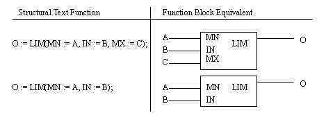
Figure 20.1 A Function with A Variable Argument List The ADD function in the previous example will add all of the arguments in any order and get the same result, but other functions are more particular. Consider the circular limit function shown in Figure 20.1 Function Argument Lists. In the first ST function the maximum MX, minimum MN and test IN values are all used. In the second function the MX value is not defined and will default to 0. Both of the ST functions relate directly to the function blocks on the right side of the figure. 
|