• Describing process control using flowcharts
• Conversion of flowcharts to ladder logic
• Ba able to describe a process with a flowchart.
• Be able to convert a flowchart to ladder logic.
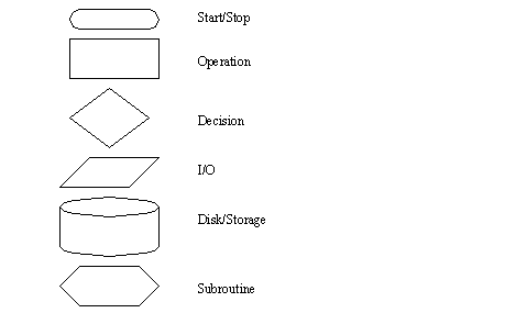
A flowchart is ideal for a process that has sequential process steps. The steps will be executed in a simple order that may change as the result of some simple decisions. The symbols used for flowcharts are shown in Figure 10.1 Flowchart Symbols. These blocks are connected using arrows to indicate the sequence of the steps. The different blocks imply different types of program actions. Programs always need a start block, but PLC programs rarely stop so the stop block is rarely used. Other important blocks include operations and decisions. The other functions may be used but are not necessary for most PLC applications.

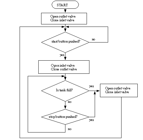
A flowchart is shown in Figure 10.1 A Flowchart for a Tank Filler for a control system for a large water tank. When a start button is pushed the tank will start to fill, and the flow out will be stopped. When full, or the stop button is pushed the outlet will open up, and the flow in will be stopped. In the flowchart the general flow of execution starts at the top. The first operation is to open the outlet valve and close the inlet valve. Next, a single decision block is used to wait for a button to be pushed. when the button is pushed the yes branch is followed and the inlet valve is opened, and the outlet valve is closed. Then the flow chart goes into a loop that uses two decision blocks to wait until the tank is full, or the stop button is pushed. If either case occurs the inlet valve is closed and the outlet valve is opened. The system then goes back to wait for the start button to be pushed again. When the controller is on the program should always be running, so only a start block is needed. Many beginners will neglect to put in checks for stop buttons.

Figure 10.1 A Flowchart for a Tank Filler
The general method for constructing flowcharts is:
2. Determine the major actions, these are drawn as blocks.
3. Determine the sequences of operations, these are drawn with arrows.
4. When the sequence may change use decision blocks for branching.
Once a flowchart has been created ladder logic can be written. There are two basic techniques that can be used, the first presented uses blocks of ladder logic code. The second uses normal ladder logic.