27.3 FINITE ELEMENT MODELS
������������
Consider a central node 'i' connected to neighboring nodes with springs.
Equations can be written to relate the position of node i to the surrounding nodes and the applied force. The 'x' and 'y' values are deflections from the unloaded state. The 'Ks' value is based on the material stiffness and the geometry of the elements.
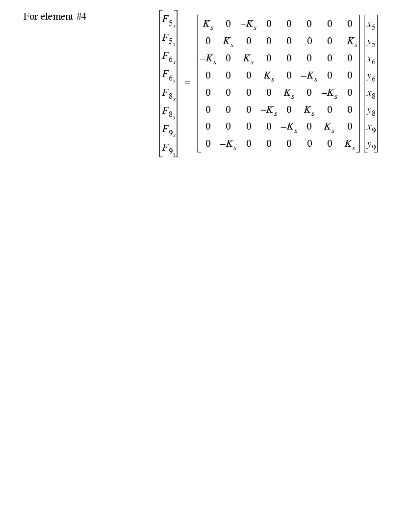
This can be combined into a more
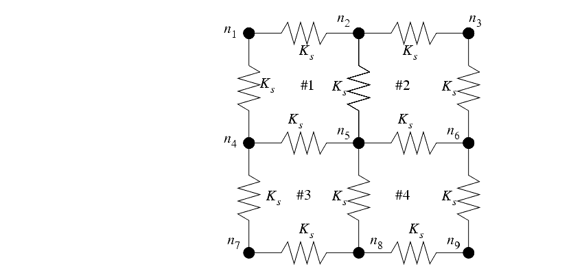
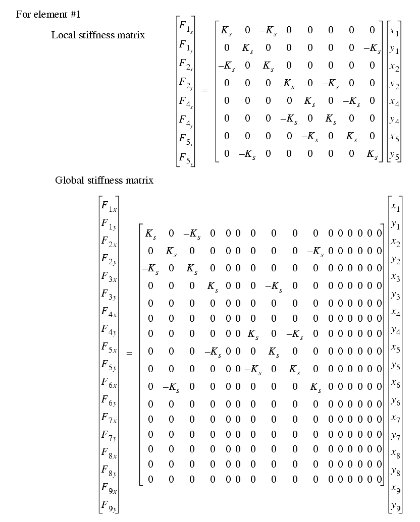
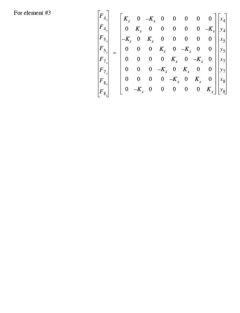
A four element mesh
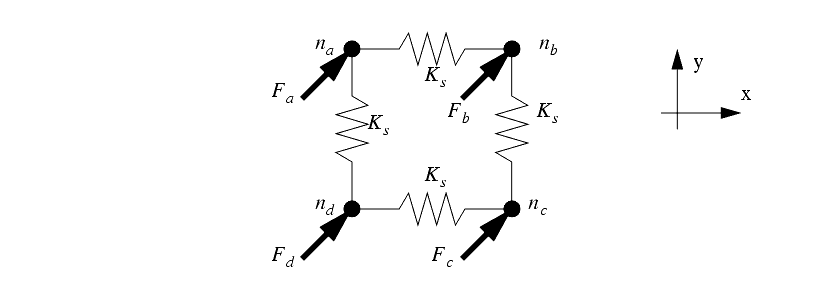
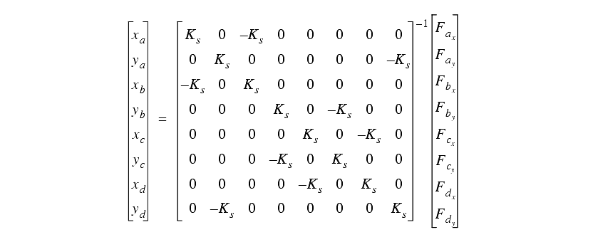
If the input forces are known, then the resulting displacements of the nodes can be calculated by inverting the matrix. Consider the matrix for a single node.
If we assume that node 'c' is fixed in the 'x' and 'y' directions, the matrix can reflect this by setting the appropriate matrix rows to zero.
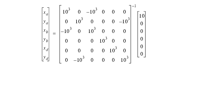
The displacements can then be found by selecting values for the coefficents and solving the matrix. We can select a value of 1000 for the stiffness, and a force of 10 will be applied at point 'a' in the positive 'x' direction.
This method generates very large matrices, easily into the millions.
To reduce the matrix size techniques such as symmetry are commonly used.
Strains can be found by calculating the relative displacements of neighboring points. These can then be used to calculate the stresses.
More complex elements are commonly used depending upon the stress conditions, part geometry and other factors.
There are a variety of finite element element methods and applications
Computation Fluid Dynamics
