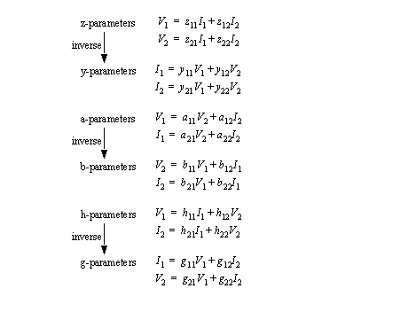
• Two port networks are a useful tool for describing idealized components. The basic device schematics are simple, but each set of parameters views the device differently.
• The basic device is seen below, along with the various parameter sets,


• obviously some of the parameters are impedance, while others are admittance. They can be easily determined by setting other parameters to zero, and measuring relevant voltages/currents.

• The equivalent circuit for the z-parameters is shown below,

• If one set of parameters is known, other parameters can be found using simple conversions. This can help when one set of parameters is needed, but cannot be measured directly.
• Simple cases of networks are reciprocal and symmetrical. When a network is neither of these, then it typically has active components, dependent sources, etc.
• If a voltage is applied at one port, the short circuit current out the other port will be the same, regardless of which side the voltage is applied to.
• Reciprocal networks are only possible when passive elements are used.
• The parameters that indicate a reciprocal networks are,

• With any reciprocal network we only need to find 3 of the four parameters, the last can be determined mathematically.
• This is a special case of the reciprocal network where the input and output parameters are identical.
• In addition to the reciprocal constraints, we must also consider,

• Only two of these parameters need to be found to find the other two parameters.
• When connecting networks, various parameters add ease.
• The a parameters can be multiplied

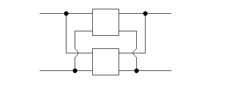
• With this type of connection the parameters are added,

• Here the devices are connected,
