
• In controller design we try to meet some objective. Typical objectives include,
positioning: for moving from position to position, where the setpoint is changed suddenly
tracking: for following paths where setpoints are constantly changing
disturbance resistant: unexpected variations can be compensated for
multi-stage: for complex systems that need small errors
feed forward disturbance: can reduce effects of disturbances
feed forward command: to follow complex motions
cascade: a controller that examines intermediate steps of a process
• typical constraints to be developed are,
stability: does not diverge over time
stability: sampling period is short enough (no-aliasing)
realizable: does not refer to future values
• In these systems we will focus on how the output relates to the input.
• These techniques work best with simple systems that require a jump from one setpoint to another.
• The general procedure to design a controller is,
1. Model the process (i.e., find Gp)
2. Determine the control objective (i.e. select the desired system response Gdr)
3. Substitute these into the equation below and solve for the controller transfer function,

4. Check the equation for practicality and stability
5. Develop the control equation for the computer
Problem 2.1 Try to derive the expression given above,

• It is possible (for a first order process) to match the output function to the input function in one step.

Problem 2.2 Given the process model below, design a deadbeat controller,

• Trying to eliminate the error in one step can require an extremely high (power) gain. When this gain is excessive we may use a less powerful controller.
• The following programs are examples of methods for programming using a few common languages.
• These examples are for the Computer Boards DAS08-AOM board (The boards we used in the lab with Labview).
• Please note that these programs have not been debugged.
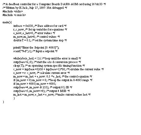
• A simple example of the deadbeat controller is given below. This can be converted to many of the ‘modern’ version of basic that have appeared. Comments have been added to help clarify the operation

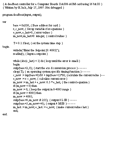
• The example program below should implement the deadbeat controller example given in this section,
• The example program below should implement the deadbeat controller example given in this section,
Problem 2.3 As an exercise, implement the controller on a Basic Stamp chip. (note: this program will be similar to all others)
• The deadbeat controller can call for extremely high gains, but this requires a high level of power not commonly found in engineered systems.
• When we want to slow down the system response so that it occurs over a number of controller steps, we can replace the deadbeat (one time step) function with a gradual first order reduction (exponential decay) over a number of time steps.
• This gradual response will use a time constant to produce the rate of response (recall that the difference between input and output is reduced 63% for each duration of the time constant).
• The general form of this relationship is seen below,

• Consider the example for the deadbeat controller,
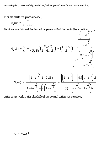
Problem 2.4 Assume the response time constant should be 1.0 seconds, and the sampling time is 0.2 seconds, develop the final form of the controller.

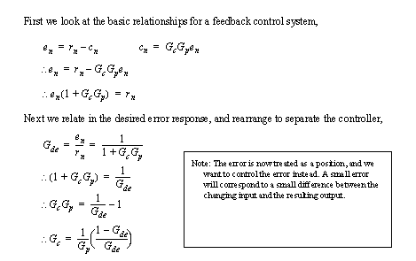
• In tracking controllers we assume that the setpoint will be moving. As a result we will focus on a desired error function, instead of an overall transfer function.
• To do this we must first develop a function that relates the elements of the control loop, to the desired error response,
• Specific controllers can be developed using the relationships used for the positioning controllers.
• As an example tracking control would be needed in your hand for curved letters, positioning would result in block letters.
• The method behind this controller is very similar to the deadbeat controller, we try to eliminate the error in a single step,
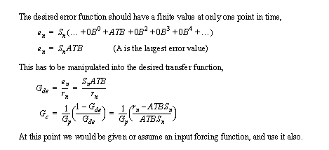
Problem 2.5 Find a controller for the transfer function given below, assuming a ramped input with a sampling time of 0.2 seconds. Use a maximum error of 0.02.

• In real systems we expect that certain events will occur that are not part of our system model.
• In this case we assume that the system control is happening as expected, and we add in a new disturbance input.
• The block diagram below shows one of these systems, with a disturbance injected between the controller and the process.
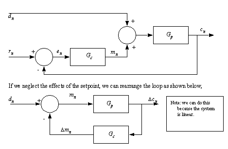
• Notice that in the above form we are reducing the problem by finding differences (basically a partial differential solution) which will be a good approximation when the disturbance is not too fast or large.
• We can develop an equation for the controller, based on the desired system response to the disturbance,

• The closed form expression can be calculated by replacing the desired transfer function,

• These systems are often called regulators, and can be used when a system is subject to unexpected noise. Examples of possible applications would include plumbing systems, electrical power supplies, etc.
• We can use an approach similar to the deadbeat controller, but we still need to know the type of disturbance expected to develop a controller.

• Consider a case where the disturbance is a step function

• We can examine the previous controller for stability as well,

• If we have a first order system we only need to have a sample time that is shorter than the system time constant.
• It can sometimes be helpful to have more than one controller in a system.
• In feedforward controllers we have one controller to deal with an input value, and a second to control error.
• In cascade control we break the control into segments, that take advantage of readings within the process.
• When a system has a disturbance that can be measured we can add a controller that specifically compensates.
• The figure below shows a feedforward disturbance controller,

• In this case ‘F(B)’ is a function of how the disturbance actually effects the system. But ‘Gf’ is the controller to compensate. First, we need a model of ‘F(B)’. Next the controller ‘Gf’ is,

• The error controller is designed as if the disturbance is not present.
• This system is well suited to systems with large measurable disturbances. For example we could measure cutting force, and adapt an axis controller on a CNC machine.
• By separating out error control, and process modeling functions we can make a system that is more accurate, with reduced steady state error.
• This technique may be used when we have a process model, and the input will not be changing suddenly (The feedback error controller will tend to overcompensate).
• We do this using a system of the form below,

• The relevant transfer functions are,
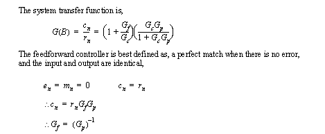
• The feedback error controller can be selected to reduce the errors. The typical design technique is, to design for minimal error or disturbance.
Problem 2.6 Develop the system transfer function (given before) for a command feed forward controller

• By adding extra feedback loops we can add levels of robustness to a control system.
• In this case the control loops appear to be nested.
• Consider a cascade control system for disturbances,
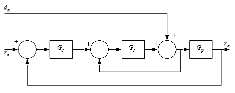
• Now consider a cascade controller for a multistage process, such as a sewage treatment plant with sequential tanks with varying flow rates. Here the disturbance would be the sewage flowing into the first tank. the two process blocks are the treatment tanks. The output is water returned to rivers The controllers vary the flow rates by looking at parameters for both tanks.
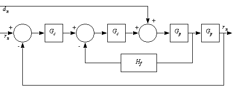
• To do design/analysis for these controllers we do an analysis of the innermost feedback loop. This then becomes a process, and we do design/analysis at the next higher loop.
Problem 2.7 Select controllers for the system pictured below,

• In deadbeat type controllers we do not typically see mentions of the sample period, but in most practical systems we see a mention of the sample time ‘T’.
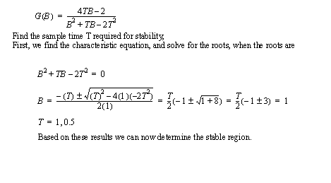
• We can use the system transfer function to calculate the acceptable range of controller time. In all cases the lower sample period is 0, but for practical reasons we may want to make this larger.
• A shorter sample time requires a faster computer, and steals cycle time from other processes.
1. Find the characteristic equation of the overall system transfer function.
2. Determine the roots (symbolically) of the equation.
3. Select values of ‘T’ that ensure that all of the roots have a value of 1 or more.
4. Select a sample time that is less than the longest time.
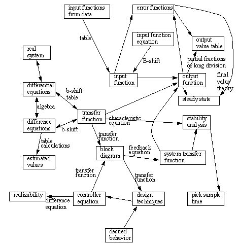
• The following is a map of techniques that show typical uses of the mathematical technique covered so far.
Problem 2.8 a) We are developing a freight elevator control system. The first major task is developing a height positioning controller. The elevator is moved to a new floor by issuing a step function for the new floor height. The transfer function below relates the voltage supplied to the elevator motor to the height of the elevator. Develop a controller transfer function that has a first order response, and draw a complete block diagram.

b) Develop the discrete equation for the controller if the time constant for the first order response is 5 seconds and the sampling time is 1 second.
Problem 2.9 2. c) Write a computer program (in the computer language of your choice) that implements the controller in question 1. Assume the input and output values are set using the two functions below.

Problem 2.10 Redraw the following system and add a feedforward controller. Develop the function used for the feed forward controller.

Problem 2.11 The control system below will be used for positioning the height of an elevator.

a) Find a controller transfer function that gives a first order response for a time step of T=1 and a time constant of 3.
b) Develop the discrete equation and determine if the controller is realizable.
c) Develop a transfer function for the final system and determine if the system is stable.

Problem 2.12 We want to design a control system to minimize the effects of disturbance. Given a step input of magnitude 1, we are willing to accept a maximum error of 0.5 for one time step.

a) Find a controller transfer function.
b) Develop the discrete equation for the system and determine if the controller is realizable?