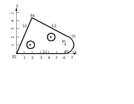
• This language was originally designed to be read from paper tapes. As a result it is quite simple.
• The language directs tool motion with simple commands
• Note, I show programs with spaces to improve readability, but these are not necessary.
• A basic list of ‘G’ operation codes is given below. These direct motion of the tool.
G00 - Rapid move (not cutting)
G02 - Clockwise circular motion
G03 - Counterclockwise circular motion
G05 - Pause (for operator intervention)
G17 - x-y plane for circular interpolation
G18 - z-x plane for circular interpolation
G19 - y-z plane for circular interpolation
G20 - turning cycle or inch data specification
G21 - thread cutting cycle or metric data specification
G25 - wait for input #1 to go low (Prolight Mill)
G26 - wait for input #1 to go high (Prolight Mill)
G28 - return to reference point
G29 - return from reference point
G31 - Stop on input (INROB1 is high) (Prolight Mill)
G33-35 - thread cutting functions (Emco Lathe)
G35 - wait for input #2 to go low (Prolight Mill)
G36 - wait for input #2 to go high (Prolight Mill)
G40 - cutter compensation cancel
G41 - cutter compensation to the left
G42 - cutter compensation to the right
G43 - tool length compensation, positive
G44 - tool length compensation, negative
G70 - set inch based units or finishing cycle
G71 - set metric units or stock removal
G72 - indicate finishing cycle (EMCO Lathe)
G72 - 3D circular interpolation clockwise (Prolight Mill)
G73 - turning cycle contour (EMCO Lathe)
G73 - 3D circular interpolation counter clockwise (Prolight Mill)
G74 - facing cycle contour (Emco Lathe)
G74.1 - disable 360 deg arcs (Prolight Mill)
G75 - pattern repeating (Emco Lathe)
G75.1 - enable 360 degree arcs (Prolight Mill)
G76 - deep hole drilling, cut cycle in z-axis
G78 - multiple threading cycle
G81-89 - fixed cycles specified by machine tool manufacturers
G81 - drilling cycle (Prolight Mill)
G82 - straight drilling cycle with dwell (Prolight Mill)
G83 - drilling cycle (EMCO Lathe)
G83 - peck drilling cycle (Prolight Mill)
G84 - taping cycle (EMCO Lathe)
G85 - reaming cycle (EMCO Lathe)
G85 - boring cycle (Prolight mill)
G86 - boring with spindle off and dwell cycle (Prolight Mill)
G89 - boring cycle with dwell (Prolight Mill)
G90 - absolute dimension program
G93 - Coordinate system setting
G94 - Feed rate in ipm (EMCO Lathe)
G95 - Feed rate in ipr (EMCO Lathe)
G96 - Surface cutting speed (EMCO Lathe)
G97 - Rotational speed rpm (EMCO Lathe)
G98 - withdraw the tool to the starting point or feed per minute
G99 - withdraw the tool to a safe plane or feed per revolution
G101 - Spline interpolation (Prolight Mill)
• M-Codes control machine functions and these include,
M01 - optional stop using stop button
M08 - turn on accessory #1 (120VAC outlet) (Prolight Mill)
M09 - turn off accessory #1 (120VAC outlet) (Prolight Mill)
M10 - turn on accessory #2 (120VAC outlet) (Prolight Mill)
M11 - turn off accessory #2 (120VAC outlet) (Prolight Mill) or tool change
M20 - tailstock back (EMCO Lathe)
M20 - Chain to next program (Prolight Mill)
M21 - tailstock forward (EMCO Lathe)
M22 - Write current position to data file (Prolight Mill)
M25 - set output #1 off (Prolight Mill)
M26 - close chuck (EMCO Lathe)
M26 - set output #1 on (Prolight Mill)
M35 - set output #2 off (Prolight Mill)
M36 - set output #2 on (Prolight Mill)
M38 - put stepper motors on low power standby (Prolight Mill)
M47 - restart a program continuously, or a fixed number of times (Prolight Mill)
M71 - puff blowing on (EMCO Lathe)
M72 - puff blowing off (EMCO Lathe)
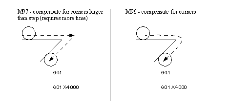
M96 - compensate for rounded external curves
M97 - compensate for sharp external curves
M99 - return from subprogram, jump instruction
M101 - move x-axis home (Prolight Mill)
M102 - move y-axis home (Prolight Mill)
M103 - move z-axis home (Prolight Mill)
• Other codes and keywords include,
Annn - an orientation, or second x-axis spline control point
Bnnn - an orientation, or second y-axis spline control point
Cnnn - an orientation, or second z-axis spline control point, or chamfer
Fnnn - a feed value (in ipm or m/s, not ipr), or thread pitch
Innn - x-axis center for circular interpolation, or first x-axis spline control point
Jnnn - y-axis center for circular interpolation, or first y-axis spline control point
Knnn - z-axis center for circular interpolation, or first z-axis spline control point
Lnnn - arc angle, loop counter and program cycle counter
Onnn - subprogram block number
Pnnn - subprogram reference number
Rnnn - a clearance plane for tool movement, or arc radius, or taper value
Qnnn - peck depth for pecking cycle
Snnn - cutting speed (rpm), spindle speed
; - starts a comment (proLight Mill), or end of block (EMCO Lathe)
• The typical sequence of one of these programs is,
1. Introductory functions such as units, absolute coords. vs. relative coords., etc.
5. Cutting tool movements and tool changes
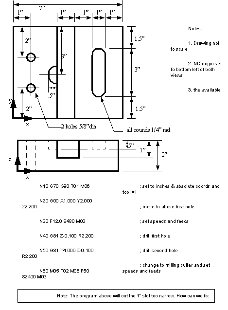
• A program is given for the sample part below. Complete the last few lines.

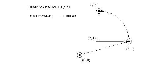
• The following is an example of circular interpolation. This is valid for both milling and turning. Note that here we move to the start point, the command indicates the direction (clockwise or counterclockwise). The I, J values indicate the center of rotation, and the X, Y values indicate the point to stop at. We can also cut circular paths on other planes by resetting the cutting planes (G17, G18, G19).
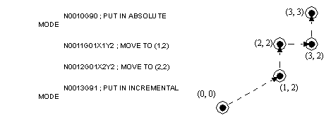
• When cutting, it is useful to change our point of reference. When doing mathematics we tend to dimension relative to a main origin (absolute). In fact a machine will need to have coordinates specified with reference to a main origin. But when we examine parts we tend to refer to local origins for features. (Consider how you dimension details on a drawing.) These relative points refer to as local origins. We can also do moves as distances to the next point.
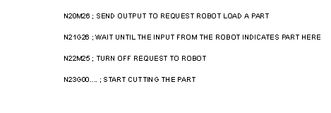
• When using the prolight mill we can add program elements to request that an external device (ie robot) load or unload parts. We will assume that the robot has been connected to the robotic interface port available. This port has four inputs and two outputs. The example below assumes that the input #1 indicates a part has been dropped off and the mill can start. Output #1 will be turned on to request that the robot pick up a part and load new stock.
• In previous examples we calculated the cutter offsets by hand. Modern NC machines keep a record of the tool geometry. This can then be used to automatically calculate offsets (you don’t need to put the tool size in the program).
• The best way to think of tool compensation is when cutting a profile, should we be to the left or right of the line.
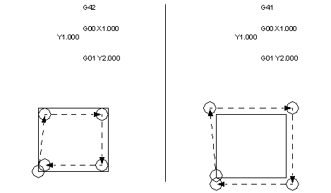
• In the previous example we notice how the shape is distorted by how the cutter navigates the corners. There are additional commands to help with these problems.
• Typical commanded cycles include,
- slot or elongated hole milling
• For practice, develop the part program for the component shown below
