7.1 CONTROL SYSTEMS
������������
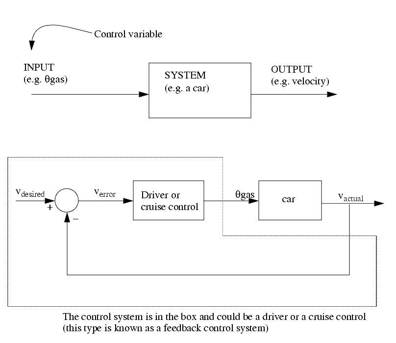
Control systems use some output state of a system and a desired state to make control decisions.
In general we use negative feedback systems because,
- they typically become more stable
- they become less sensitive to variation in component values
- it makes systems more immune to noise
Consider the system below, and how it is enhanced by the addition of a control system.
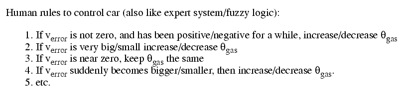
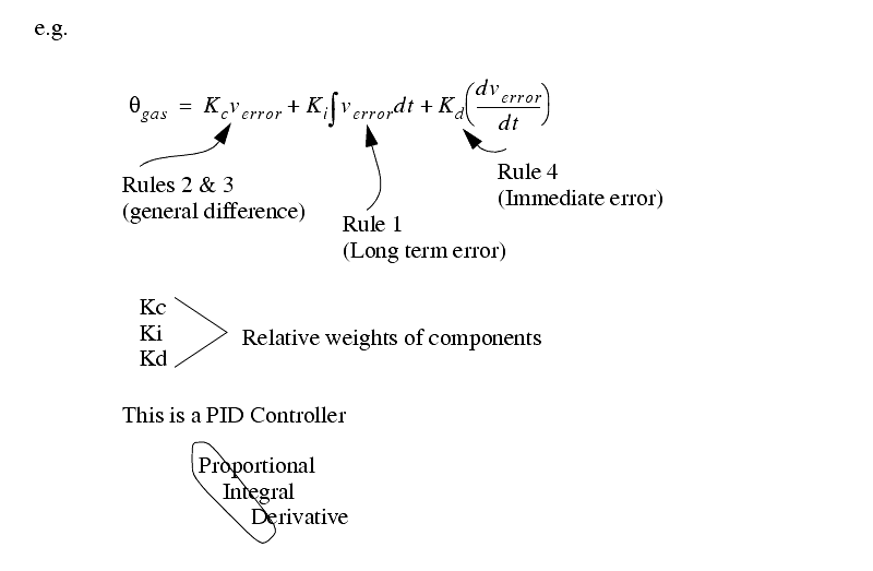
Some of the things we do naturally (like the rules above) can be done with mathematics
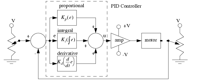
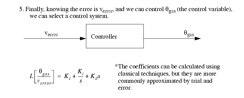
7.1.1 PID Control Systems
������������
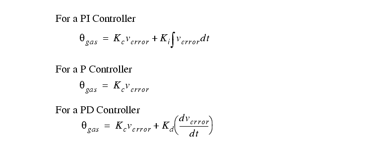
The basic equation for a PID controller is shown below. This function will try to compensate for error in a controlled system (the difference between desired and actual output values).
The figure below shows a basic PID controller in block diagram form.
The PID controller is the most common controller on the market.
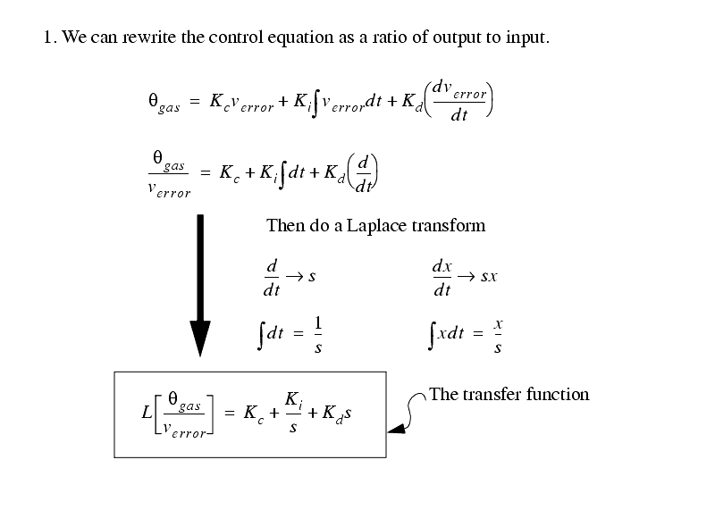
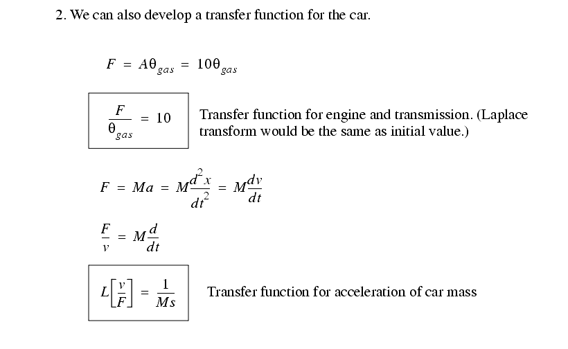
7.1.2 Analysis of PID Controlled Systems With Laplace Transforms
������������
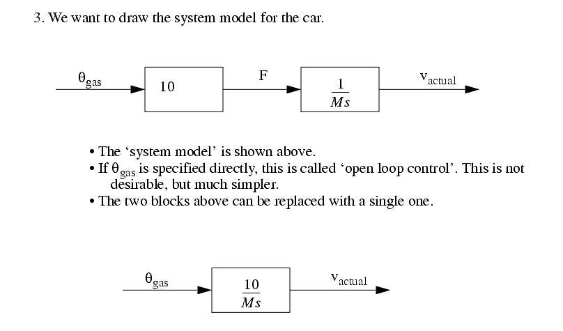
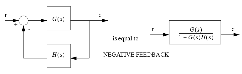
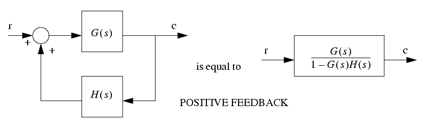
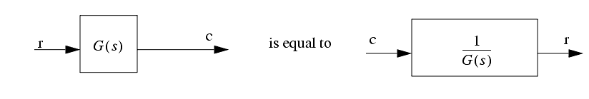
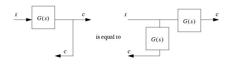
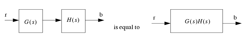
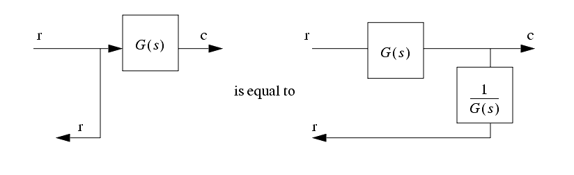
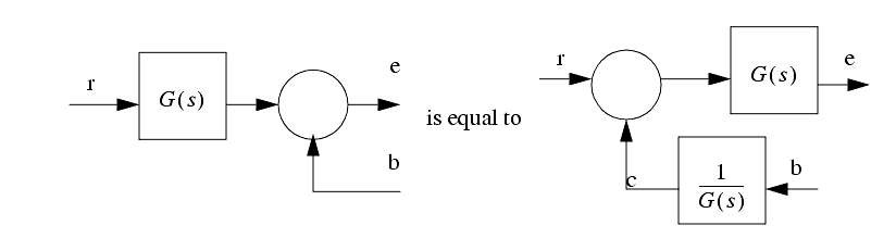
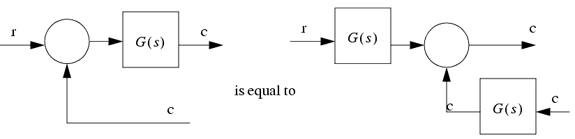
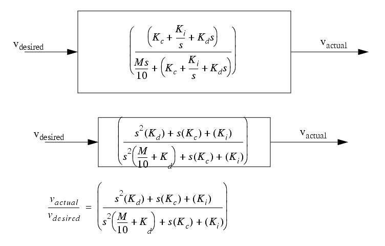
7.1.3 Manipulating Block Diagrams
������������
7.1.3.1 - Commercial PID Tuners
������������
WARNING: Don't assume results from these systems are perfect, proper engineering methods must be used to avoid failures in critical systems.
EXPERTUNE
will automatically adjust gain and time constant
LT/TUNE
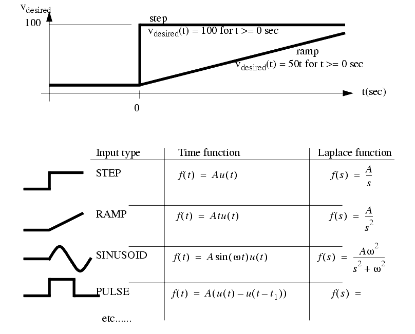
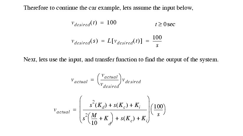
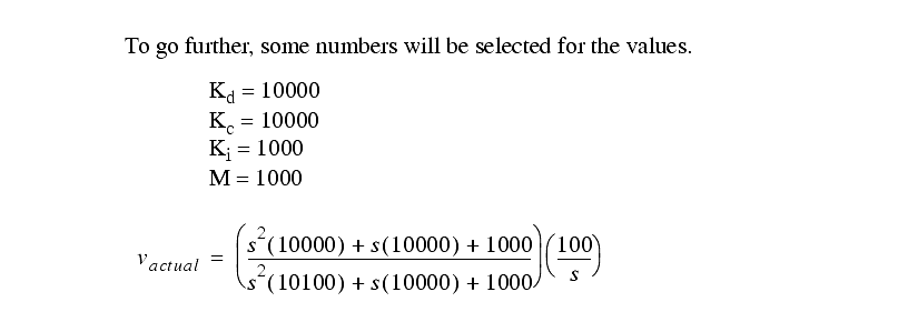
7.1.4 Finding The System Response To An Input
������������
Even though the transfer function uses the Laplace `s', it is still a ratio of input to output.
Find an input in terms of the Laplace `s'
7.1.5 System Response
������������
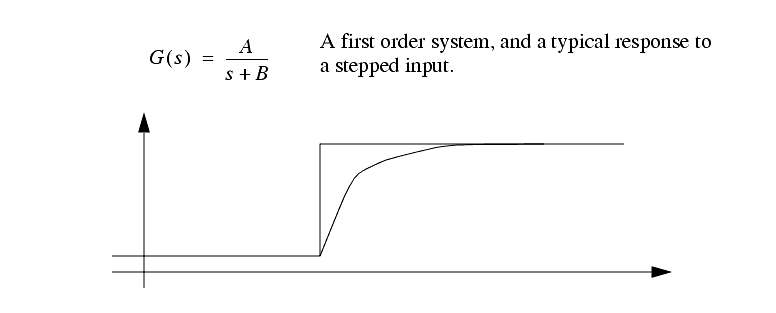
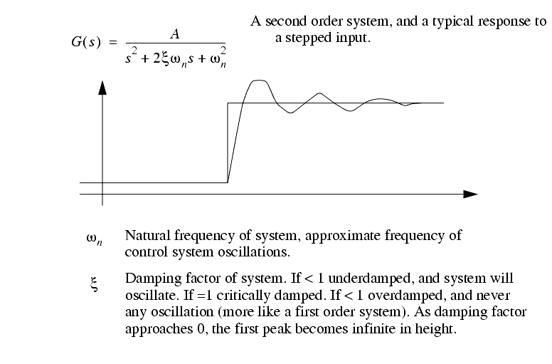
There are two very common systems assumed - first and second order.
First order systems are very simple, as is shown below.
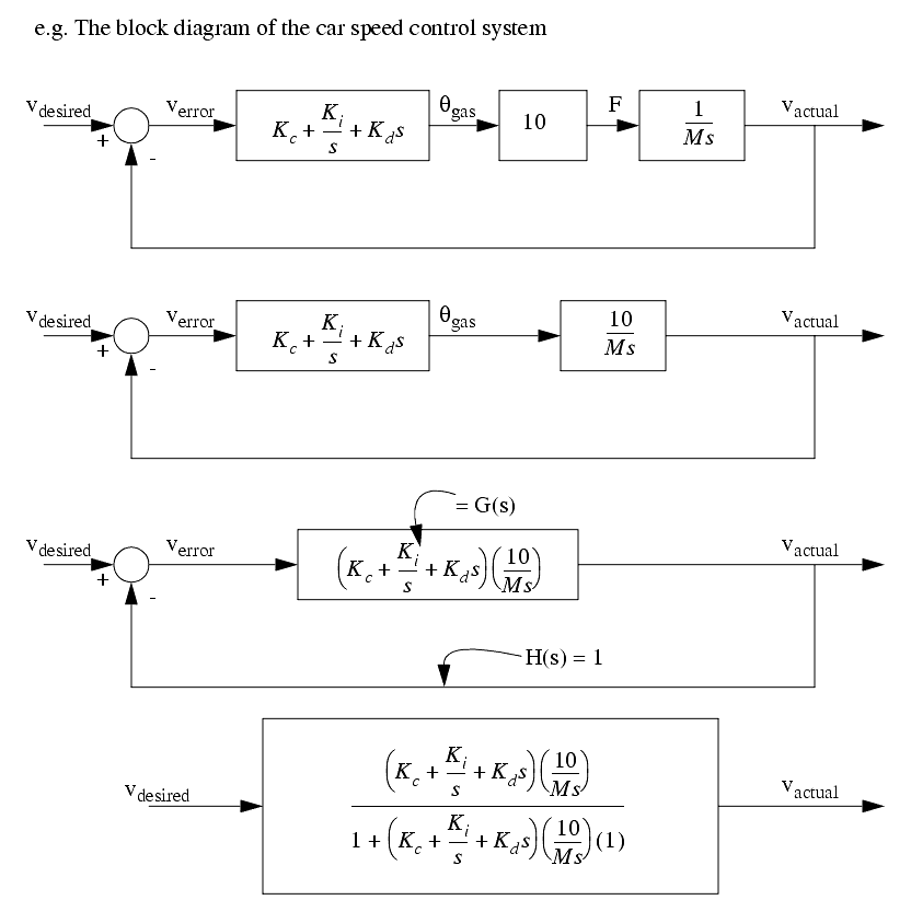
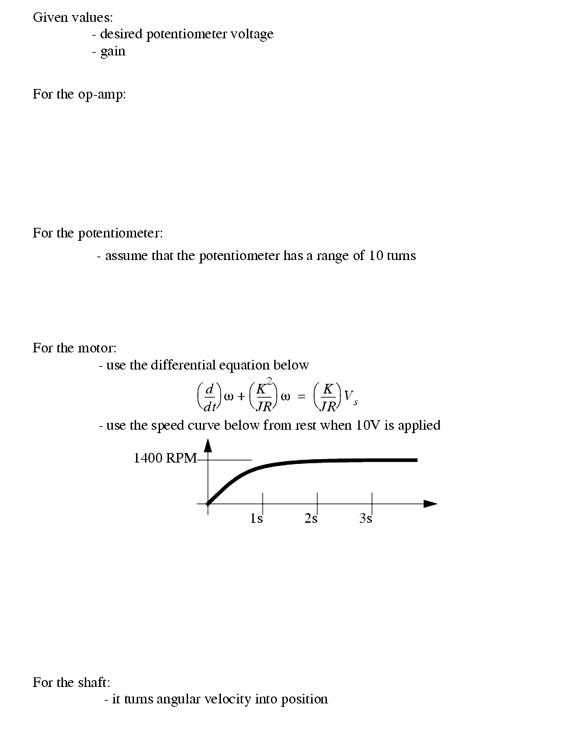
7.1.6 A Motor Control System Example
������������
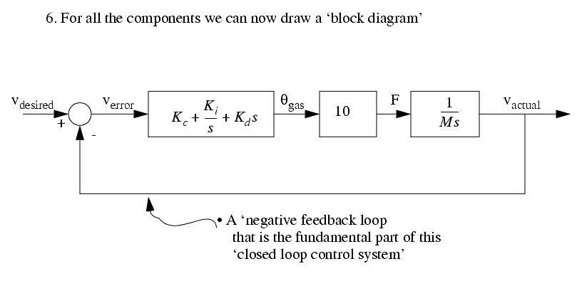
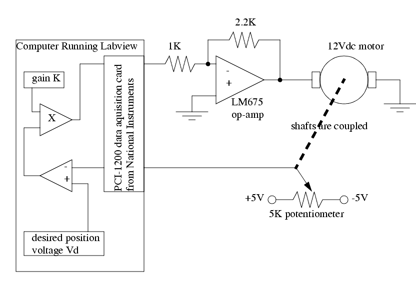
Condsider the example of a DC servo motor controlled by a computer. The purpose of the controller is to position the motor. The system below shows a reasonable control system arrangement. Some elements such as power supplies and commons for voltages are omitted for clarity.
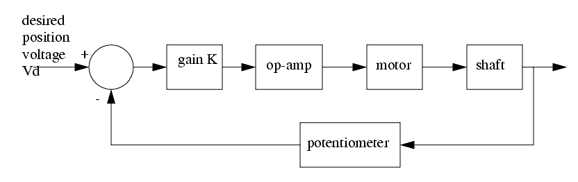
This system can then be redrawn with a block diagram.
The block diagram can now be filled out with actual values for the components. Do this below.
Convert the block diagram into a transfer function for the entire system.
Pick a value of the gain 'K' to give a system performance with the damping factor = 1.0.
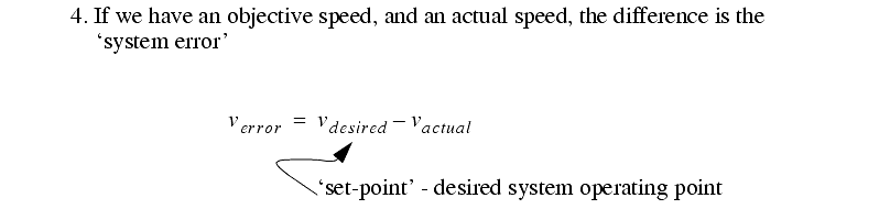
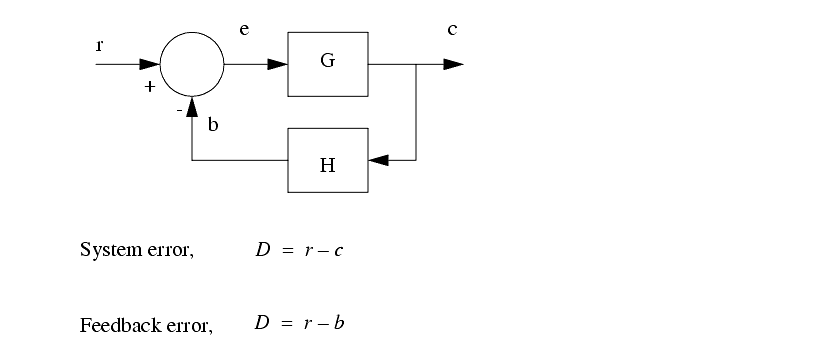
7.1.7 System Error
������������
We typically will be interested in system error and feedback error.
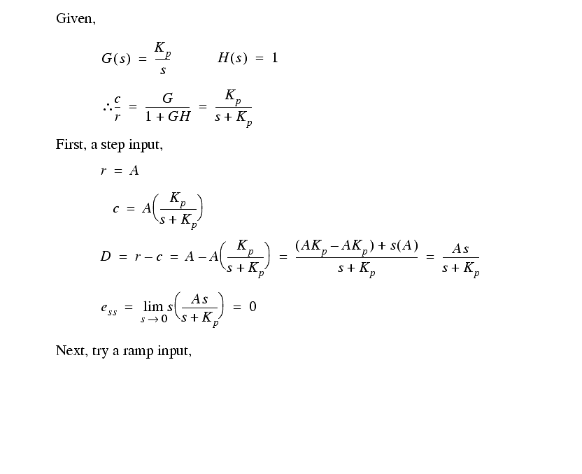
Consider a simple negative feedback system with various inputs,
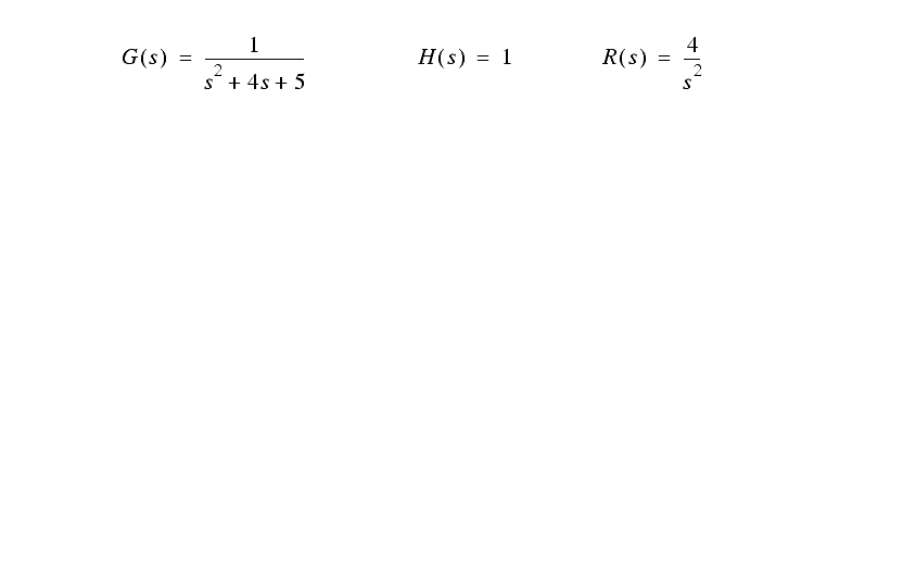
Practice problem - find the steady state system error for the transfer function and ramp below,
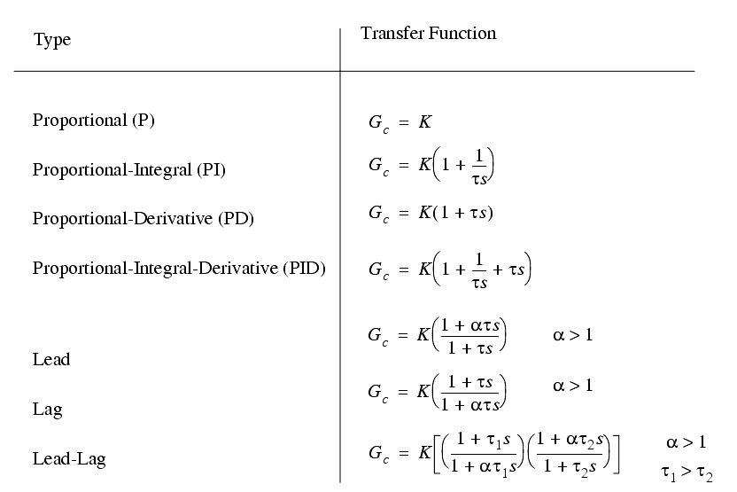
7.1.8 Controller Transfer Functions
������������
The table below is for typical control system types,