35. PROCESS MODELLING
������������
Instrumentation Symbols,
Table 2: ANSI/ISA-S5.1-1984 Instrumentation Symbols and Identification
| LETTER |
FIRST LETTER |
SECOND LETTER |
| A |
Analysis |
Alarm |
| B |
Burner, Combustion |
User's Choice |
| C |
User's Choice |
Control |
| D |
User's Choice |
|
| E |
Voltage |
Sensor (Primary Element) |
| F |
Flow Rate |
|
| G |
User's Choice |
Glass (Sight Tube) |
| H |
Hand (Manually Initiated) |
|
| I |
Current (Electric) |
Indicate |
| J |
Power |
|
| K |
Time or Time Schedule |
Control Station |
| L |
Level |
Light (pilot) |
| M |
User's Choice |
|
| N |
User's Choice |
User's Choice |
| O |
User's Choice |
Orifice, Restriction |
| P |
Pressure, Vacuum |
Point (Test Connection) |
| Q |
Quantity |
|
| R |
Radiation |
Record or Print |
| S |
Speed or Frequency |
Switch |
| T |
Temperature |
Transmit |
| U |
Multivariable |
Multifunction |
| V |
Vibration, Mechanical Analysis |
Valve, Damper, Louver |
| W |
Weight, Force |
Well |
| X |
Unclassified |
Unclassified |
| Y |
Event, State or Presence |
Relay, Compute |
| Z |
Position, Dimen sion |
Driver, Actuator, Unclassified |
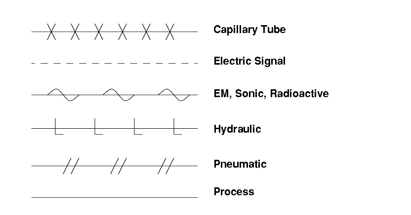
Line symbols include,
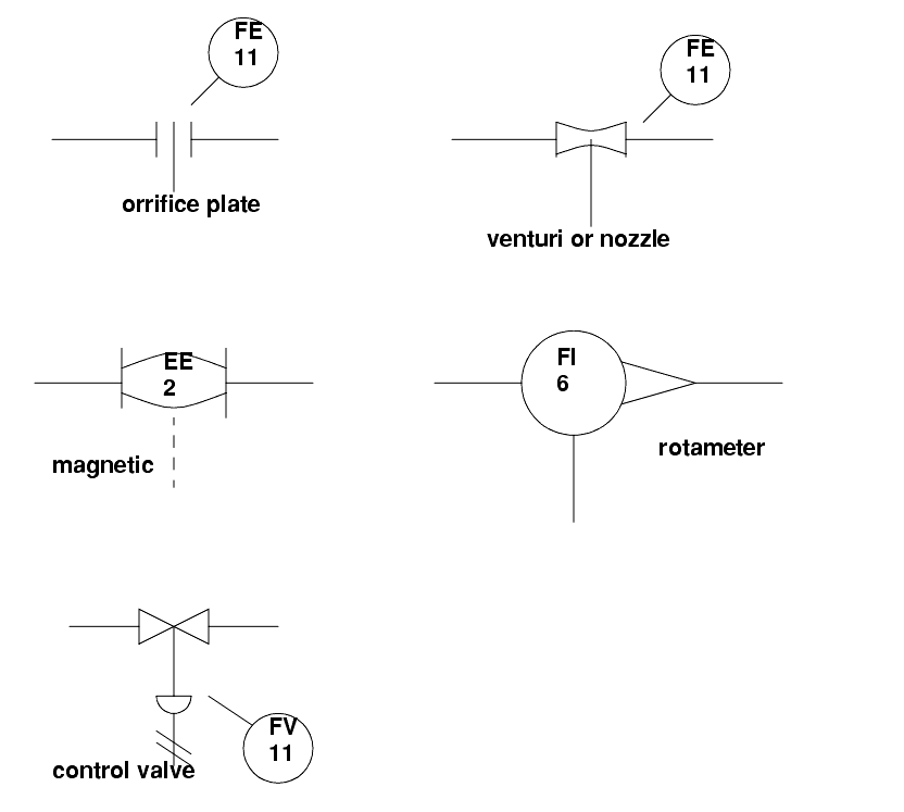
Sensor and actuator symbols include,
An example of a process diagram is given below,


