|
|
|
|
|
|
|
|
34.1 ELECTRICAL
������������34.1.1 Electrical Wiring Diagrams
������������PLC's are generally used to control the supply of power to a system. As a result, a brief examination of electrical supply wiring diagrams is worthwhile.
Generally electrical diagrams contain very basic circuit elements, such as relays, transformers, motors, fuses, lights, etc.
Within these systems there is often a mix of AC and DC power, but 3 phase AC power is what is delivered universally by electric utilities, so the wiring diagrams focus on AC circuits.
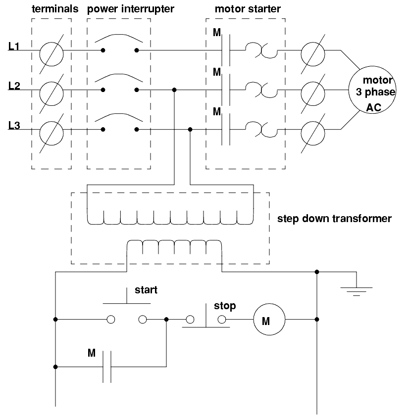
A relay diagram for a simple motor with a seal in circuit might look like the one shown below,
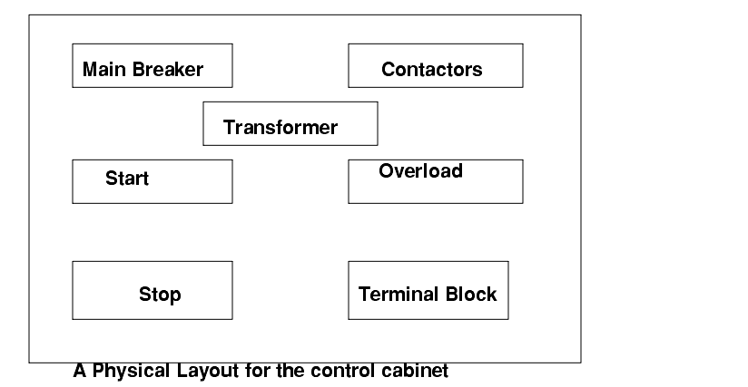
The circuit designed for the motor controller must be laid out so that it may be installed in an insulated cabinet. In the figure below, each box could be a purchased module(s).
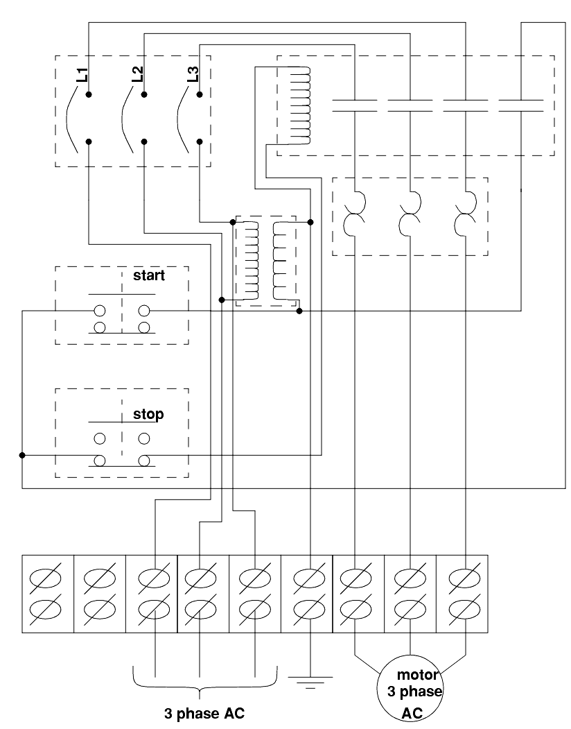
After the Layout for the cabinet is determined, the wire paths must be determined. The figure below lays out the wire paths, and modules to be used.
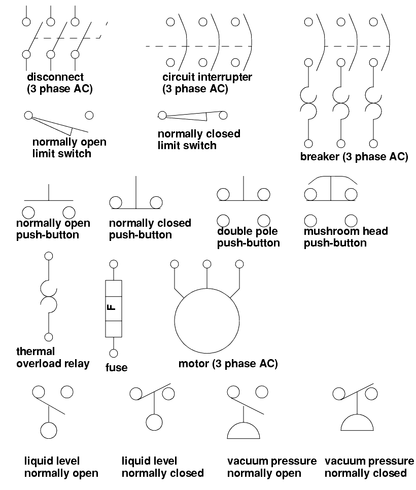
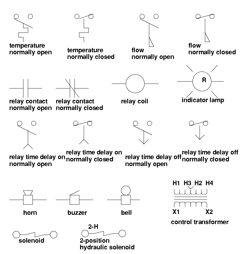
34.1.1.1 - JIC Wiring Symbols
������������The last section contained an example of an electrical control system for a motor. It used a number of symbols to represent elements.
The Joint International Committee (JIC) developed a standard set of symbols for representing electrical circuit elements. These are given below.


34.1.2 Wiring
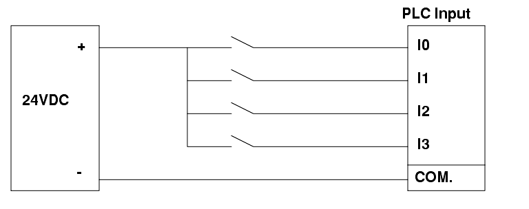
������������Discrete inputs - If a group of input voltages are the same, they can be grouped together. An example of this is shown below.
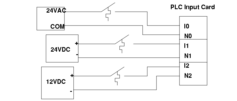
If the input voltages are different and/or come from different sources, the user might use isolated inputs.
34.1.3 Shielding and Grounding
������������There are two problems that occur in these systems,
1. Different power sources in the same system can cause different power supply voltages at opposite ends of a wire. As a result a current will flow, and an unwanted voltage appears. This can destroy components and create false signal levels.
2. Magnetic fields crossing the long conductors or in conductor loops can induce currents, and destroy equipment, give false readings, or add unwanted noise to analog data signals.
Typical sources of grounding and shielding problems are,
General shielding design points,
- Resistance coupled devices can have interference through a common power source, such as power spikes or brownouts caused by other devices in a factory.
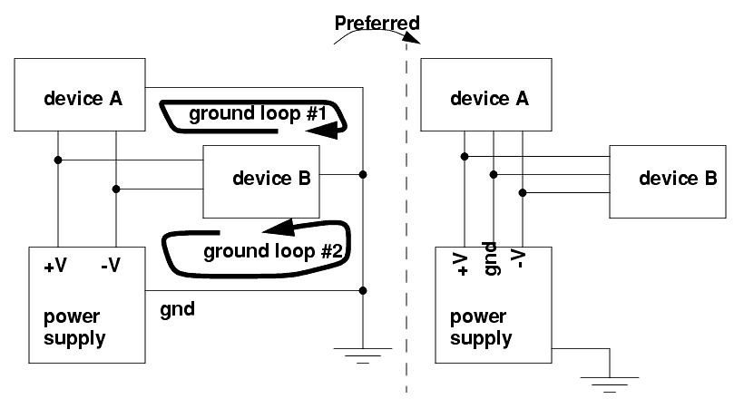
- Ground loops are caused when too many separate connections to ground are made creating loops of wire that become excellent receivers for magnetic interference that induces differences in voltage between grounds on different machines. The common solution is to use a common ground bar.
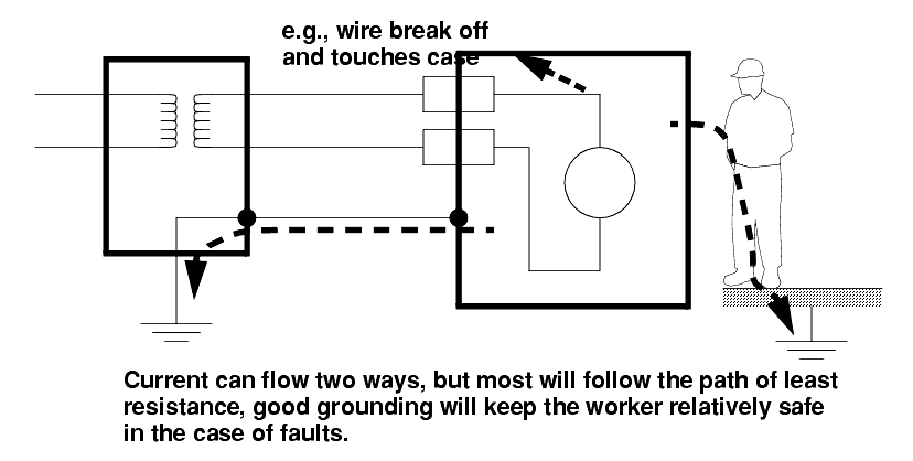
- The case of an object should be tied to ground to give current a path to follow in the case of a fault that energizes the case. (Note: fuses or breakers will cut off the power, but the fault will be on for long enough to be fatal.)
- use 12AWG stranded copper for PLC equipment grounds and 8AWG stranded copper for enclosure backplate grounds
Electrocution potential must be observed.
- Safe current levels are listed below. But be aware that in certain circumstances very low currents can kill, when in doubt, take no chances.

- Step potential is another problem. Electron waves from a fault travel out in a radial direction through the ground. If a worker has two feet on the ground at different radial distances, there will be a potential difference between the feet that will cause a current to flow through the legs. The gist of this is - if there is a fault, don't run/walk away/towards.
- Always ground systems first before applying power. (The first time a system is activated it will have a higher chance of failure.)
Fail-safe wiring should be used so that if wires are cut or connections fail, the equipment should turn off. e.g., if a normally closed stop button is used, and the connector is broken off, it will cause the machine to stop, as if the stop button has been pressed, and brake the connection.
NO (Normally open) - When wiring switches or sensors that start actions, use normally open switches so that if there is a problem the process will not start.
NC (Normally Closed) - When wiring switches that stop processes use normally closed so that if they fail the process will stop. E-Stops must always be NC, and they must cut off the master power, not just be another input to the PLC.
Search for More: |

Custom Search
|
|