|
|
|
|
|
|
|
|
24.1 ADDRESSING
������������To use advanced data functions in a PLC, we must first understand the structure of the data in the PLC memory.
There are two types of memory used in a PLC-5.
Program Files - these are a collection of 1000 slots to store up to 1000 programs. The main program will be stored in program file 2. SFC programs must be in file 1, and file 0 is used for program and password information. All other program files from 3 to 999 can be used for `subroutines'.
Data Files - This is where the variable data is stored that the PLC programs operate on. This is quite complicated, so a detailed explanation follows.
24.1.1 Data Files
������������In brief PLC memory works like the memories in a pocket calculator. The values below are for a PLC-5, although most Allen-Bradley PLCs have a similar structure.
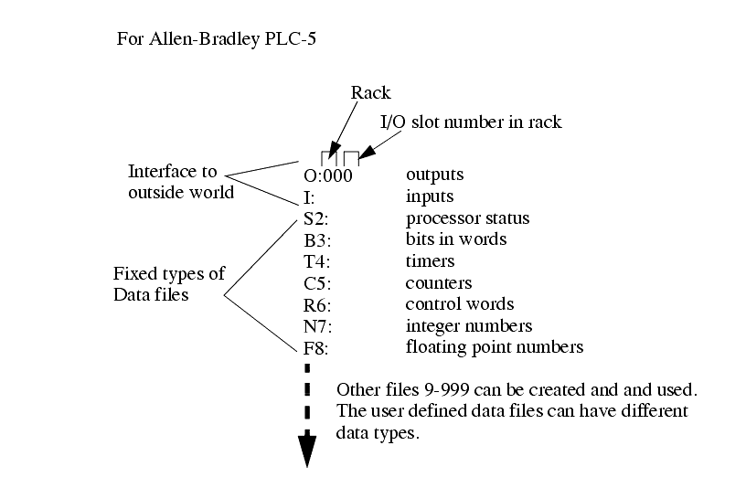
These memory locations are typically word oriented (16 bits, or 2 bytes). This includes the bit memory. But the T4, C5, R6 data files are all three words long.
All values are stored and used as integers (except when specified, eg. floating point). When integers are stored in binary format 2's complements are used to allow negative numbers. BCD values are also used.
There are a number of ways the PLC memory can be addressed,
bit - individual bits in memory can be accessed - this is like addressing a single output as a data bit
For the user assigned data files from 9 to 999 different data types can be assigned. These can be one of the data types already discussed, or another data type.
24.1.1.1 - Inputs and Outputs
������������Recall that the inputs and outputs use octal for specific bits. This means that the sequence of output bits is 00, 01, 02, 03, 04, 05, 06, 07, 10, 11, 12, 13, 14, 15, 16, 17
24.1.1.2 - User Bit Memory
������������Bit data file B3 is well suited to use of single bits. the data is stored as words and this allows two different ways to access the same bit.
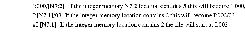
The integer file N7 stores words in 2's complement form. This allows values from -32768 to 32767. These values can be addressed as whole words, and individual bits can also be changed.
The floating point file F8 will store floating point numbers that can only be used by floating point functions. The structure of these numbers does not allow bit access.
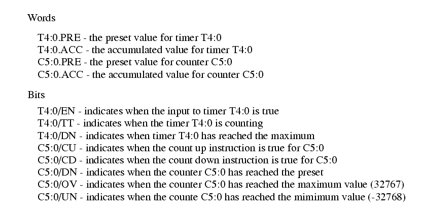
24.1.1.3 - Timer Counter Memory
������������Timer T4 values are addressed using the number of the timers, and an associated data type. For example the accumulator value of timer 3 is T4:3.ACC or T4:3/ACC.
Counter C5 values are addressed using the number of the counters, and an associated data type. For example the accumulator value of counter 3 is C5:3.ACC or C5:3/ACC.
The values for the timers and counters can be accesses directly.
24.1.1.4 - PLC Status Bits (for PLC-5s and Micrologix)
������������Some of the more commonly useful status bits in data file S2 are given below. Full listings are given in the manuals.
24.1.1.5 - User Function Control Memory
������������Control file R6 is used by various functions to track progress. Values that are available are, listed below. The use of these bits is specific to the function using the control location.
Different bits will use these memory locations differently. It will be rare for any instruction to use all of these memory bits and words.
24.1.1.6 - Integer Memory
������������This memory can hold values from -32768 to +32767 - These values cannot be exceeded.
Decimal fractions are not allowed.
The values are stored as 2's compliment.
These values are normally stored in N7:xx by default, but new blocks of integer memory are often created in other locations.
24.1.1.7 - Floating Point Memory
������������This can hold real values with fraction in the range of +/-1.1754944e-38 to +/-3.4028237e38.
These values are always limited to 7 digits of accuracy.
Search for More: |

Custom Search
|
|