
|
|
|
29.1 ANALOG INPUTS
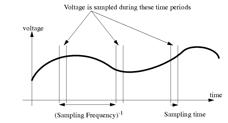
������������A Continuous signal is sampled by the computer
The computer uses approximation techniques to estimate the analog value during the sampling window.
An example of an A/D, D/A control of a process is shown below
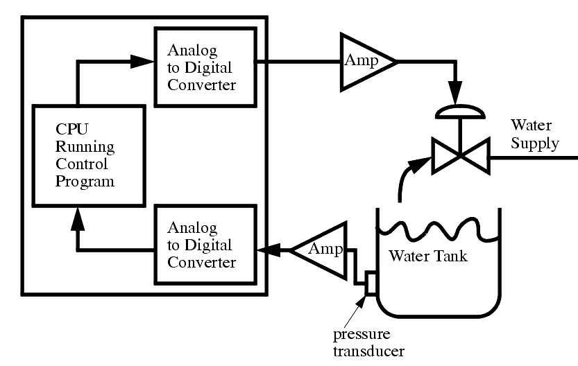
Multiplexers are used when a number of signals are to be input to a single A/D converter. This allows each of a number of channels to be sampled, one at a time
Signal conditioners are often to amplify, or filter signals coming from transducers, before they are read by the A/D converter.
Output drivers and amplifiers are often required to drive output devices when using D/A
Sampling problems occur with A/D conversion. Because readings are taken periodically (not continually), the Nyquist criterion specifies that sampling frequencies should be twice the frequency of the signal being measured, otherwise aliasing will occur.
Since the sampling window for a signal is short, noise will have added effect on the signal read. For example, a momentary voltage spike might result in a higher than normal reading.
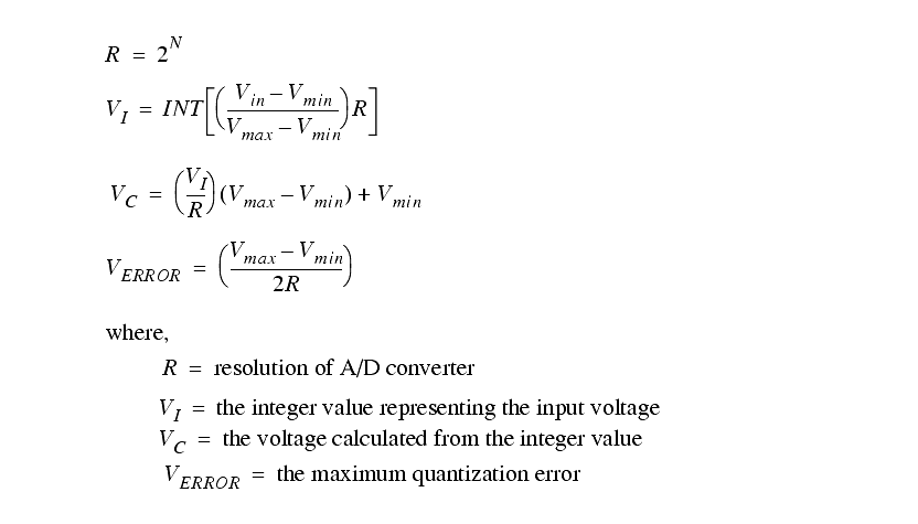
When an analog value is converted to or from digital values, a quantization error is involved. The digital numbering scheme means that for an 8 bit A/D converter, there is a resolution of 256 values between maximum and minimum. This means that there is a round off error of approximately 0.4%.
29.1.1 Analog To Digital Conversions
������������When there are analog values outside a computer, and we plan to read these to digital values, there are a variety of factors to consider,
- when the sample is requested, a short period of time passes before the final sample value is obtained.
Consider the conversion process pictured below,
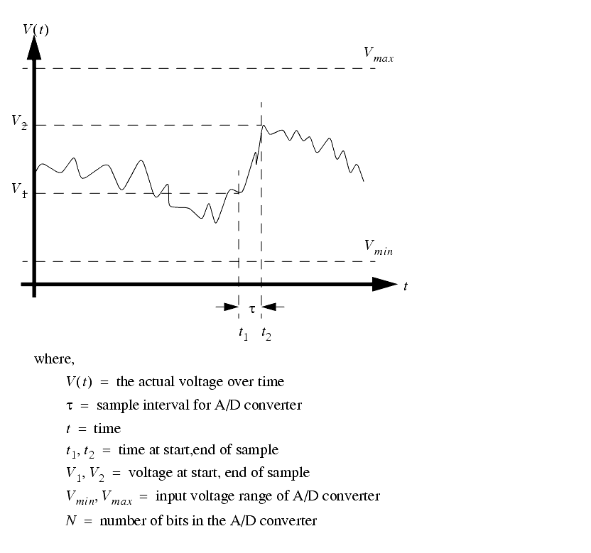
Once this signal is processes through a typical A/D converter we get the following relations (these may vary slightly for different types of A/D converters).
In most applications a sample is taken at regular intervals, with a period of `T' seconds.
In practice the sample interval is kept as small as possible. (i.e., tau << T)
If we are sampling a periodic signal that changes near or faster that the sampling rate, there is a chance that we will get a signal that appears chaotic, or seems to be a lower frequency. This phenomenon is known as aliasing.
Quite often an A/D converter will multiplex between various inputs. As it switches the voltage will be sampled by a `sample and hold circuit'. This will then be converted to a digital value. The sample and hold circuits can be used before the multiplexer to collect data values at the same instant in time.
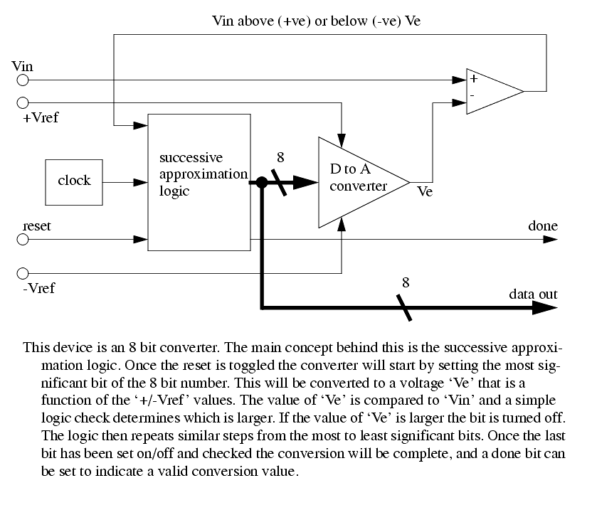
A simple type of A/D converter is shown below. It is known as a successive approximation type.
29.1.2 Analog Inputs With a PLC
������������To input analog values into a PLC we use the block transfer commands. These allow control information to the input card and retrieve results.
The example below shows ladder logic to do an analog input.
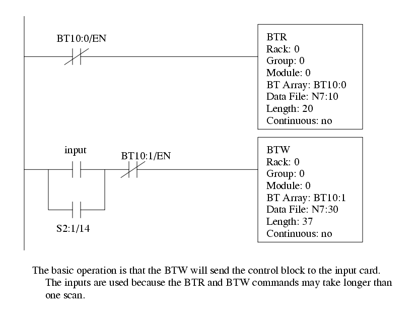
The block that needs to be written to an 1771-IFE analog input card is shown below. This is a 12 bit card, so the range will have up to 2**12 = 4096 values.
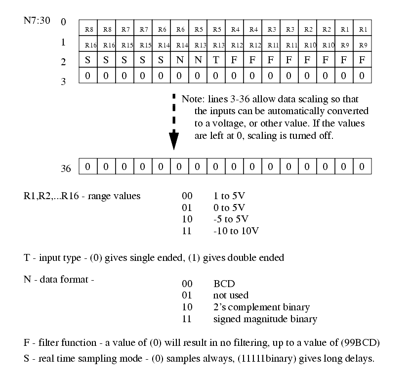
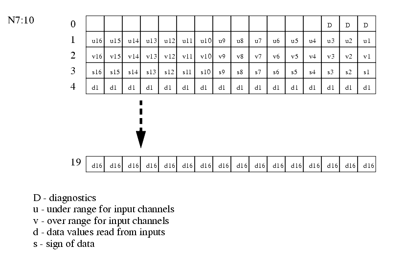
After the input card reads the values, the results are returned in a block. The structure of the block is shown below.
Search for More: |

Custom Search
|

|