3.8 ASSIGNMENT PROBLEMS
������������
1. Describe what could happen if a normally closed start button was used on a system, and the wires to the button were cut.
2. Describe what could happen if a normally open stop button was used on a system and the wires to the button were cut.
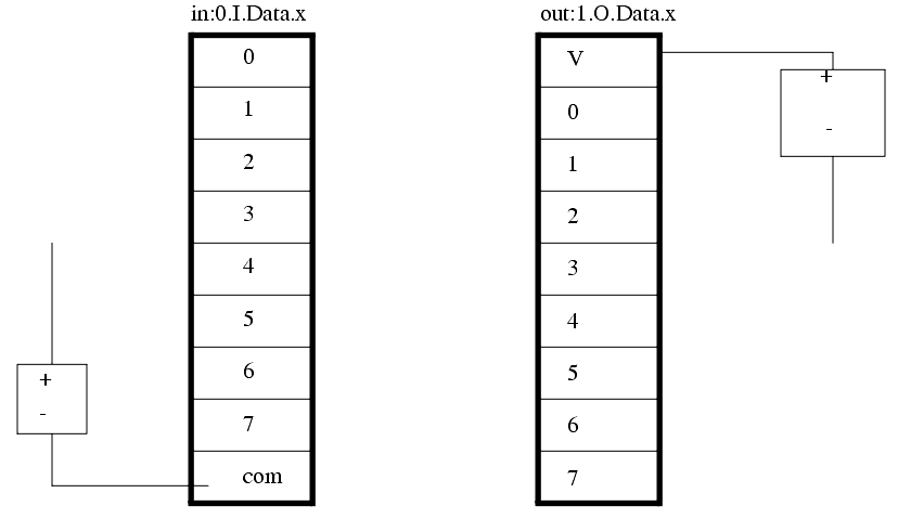
3. a) For the input ('in') and output ('out') cards below, add three output lights and three normally open push button inputs. b) Redraw the outputs so that it uses a relay output card.
4. Draw an electrical wiring (ladder) diagram for PLC outputs that are listed below.
- a solenoid controlled hydraulic valve
- a 120 Vac high current lamp
- a low current 12Vdc motor
5. Draw an electrical ladder diagram for a PLC that has a PNP and an NPN sensor for inputs. The outputs are two small indicator lights. You should use proper symbols for all components. You must also include all safety devices including fuses, disconnects, MCRs, etc...
6. Draw an electrical wiring diagram for a PLC controlling a system with both NPN and PNP input sensors. The outputs include an indicator light and a relay to control a 20A motor load. Include ALL safety circuitry.
7. Develop a wiring diagram for a system that has the following elements. Include all safety circuitry.
A 440Vac 3ph. 20HP (i.e., large) motor
8. Develop a ladder wiring diagram, including all safety circuitry that uses an PNP and an NPN input sensors. The outputs is a relay controlled AC light.
9. Draw a complete ladder wiring diagram for a PLC based control system with the following components. Include all necessary safety circuitry.
1 large 3 phase (AC) motor