9.9 PRACTICE PROBLEMS
������������
(Note: Problem solutions are available at http://sites.google.com/site/automatedmanufacturingsystems/)
1. What does edge triggered mean? What is the difference between positive and negative edge triggered?
2. Are reset instructions necessary for all timers and counters?
3. What are the numerical limits for typical timers and counters?
4. If a counter goes below the bottom limit which counter bit will turn on?
5. a) Write ladder logic for a motor starter that has a start and stop button that uses latches. b) Write the same ladder logic without latches.
6. Use a timing diagram to explain how an on delay and off delay timer are different.
7. For the retentive off timer below, draw out the status bits.
8. Complete the timing diagrams for the two timers below.
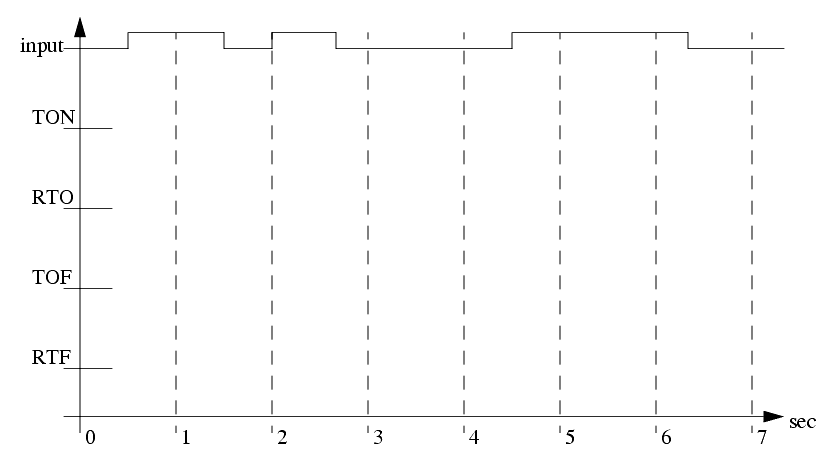
9. Given the following timing diagram, draw the done bits for all four fundamental timer types. Assume all start with an accumulated value of zero, and have a preset of 1.5 seconds.
10. Design ladder logic that allows an RTO to behave like a TON.
11. Design ladder logic that uses a timer and counter to measure a time of 50.0 days.
12. Develop the ladder logic that will turn on an output (light), 15 seconds after switch (A) has been turned on.
13. Develop the ladder logic that will turn on a output (light), after a switch (A) has been closed 10 times. Push button (B) will reset the counters.
14. Develop a program that will latch on an output (B), 20 seconds after input (A) has been turned on. The timer will continue to cycle up to 20 seconds, and reset itself, until A has been turned off. After the third time the timer has timed to 20 seconds, B will be unlatched.
15. A motor will be connected to a PLC and controlled by two switches. The GO switch will start the motor, and the STOP switch will stop it. If the motor is going, and the GO switch is thrown, this will also stop the motor. If the STOP switch was used to stop the motor, the GO switch must be thrown twice to start the motor. When the motor is running, a light should be turned on (a small lamp will be provided).
16. In dangerous processes it is common to use two palm buttons that require a operator to use both hands to start a process (this keeps hands out of presses, etc.). To develop this there are two inputs that must be turned on within 0.25s of each other before a machine cycle may begin.
17. Design a conveyor control system that follows the design guidelines below.
- The conveyor has an optical sensor
S1 that detects boxes entering a workcell
- There is also an optical sensor
S2 that detects boxes leaving the workcell
- The boxes enter the workcell on a conveyor controlled by output
C1
- The boxes exit the workcell on a conveyor controlled by output
C2
- The controller must keep a running count of boxes using the entry and exit sensors
- If there are more than five boxes in the workcell the entry conveyor will stop
- If there are no boxes in the workcell the exit conveyor will be turned off
- If the entry conveyor has been stopped for more than 30 seconds the count will be reset to zero, assuming that the boxes in the workcell were scrapped.
18. Write a ladder logic program that does what is described below.
- When button
A is pushed, a light will flash for 5 seconds.
- The flashing light will be on for 0.25 sec and off for 0.75 sec.
- If button
A has been pushed 5 times the light will not flash until the system is reset.
- The system can be reset by pressing button
B
19. Write a program that will turn on a flashing light for the first 15 seconds after a PLC is turned on. The light should flash for half a second on and half a second off.
20. A buffer can hold up to 10 parts. Parts enter the buffer on a conveyor controller by output
conveyor. As parts arrive they trigger an input sensor
enter. When a part is removed from the buffer they trigger the
exit sensor. Write a program to stop the conveyor when the buffer is full, and restart it when there are fewer than 10 parts in the buffer. As normal the system should also include a start and stop button.
21. What is wrong with the following ladder logic? What will happen if it is used?
22. We are using a pneumatic cylinder in a process. The cylinder can become stuck, and we need to detect this. Proximity sensors are added to both endpoints of the cylinder's travel to indicate when it has reached the end of motion. If the cylinder takes more than 2 seconds to complete a motion this will indicate a problem. When this occurs the machine should be shut down and a light turned on. Develop ladder logic that will cycle the cylinder in and out repeatedly, and watch for failure.


