12.4 ASSIGNMENT PROBLEMS
������������
1. Describe the difference between the block logic, delayed update, and transition equation methods for converting state diagrams to ladder logic.
2. Write the ladder logic for the state diagram below using the block logic method.
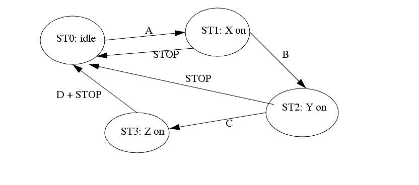
3. Convert the following state diagram to ladder logic using the block logic method. Give the stop button higher priority.
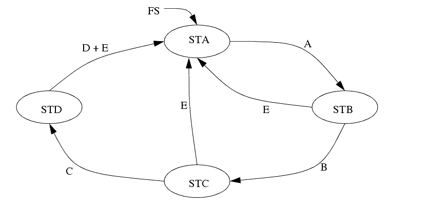
4. Convert the following state diagram to ladder logic using the delayed update method.
5. Use equations to develop ladder logic for the state diagram below using the delayed update method. Be sure to deal with the priority problems.
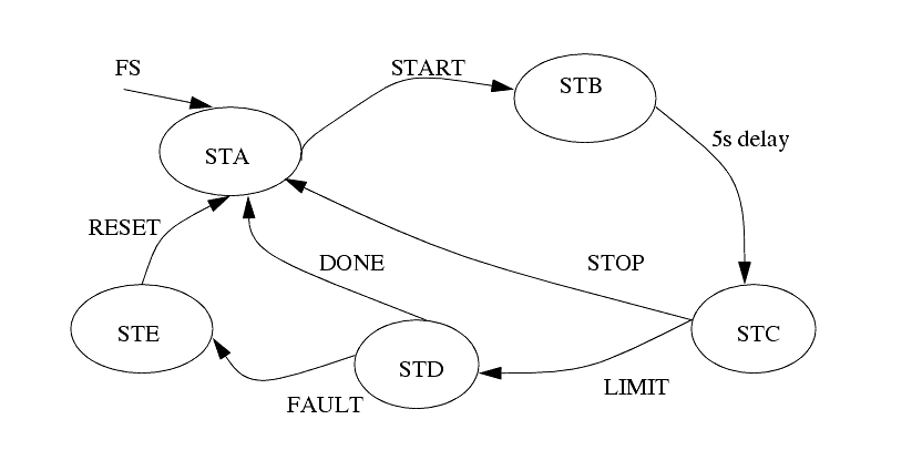
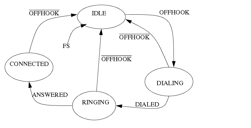
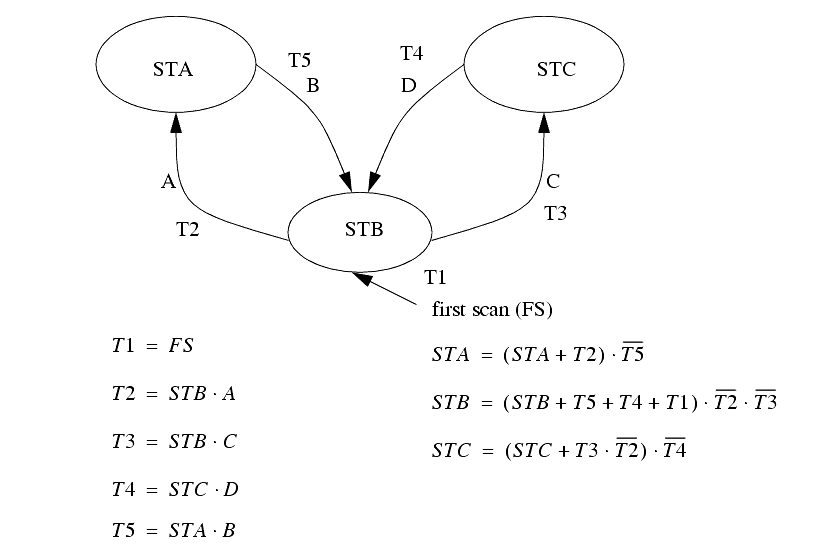
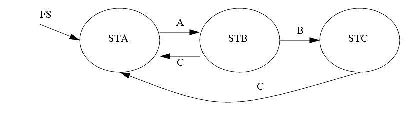
6. Implement the State-Transition equations.in the figure below with ladder logic.
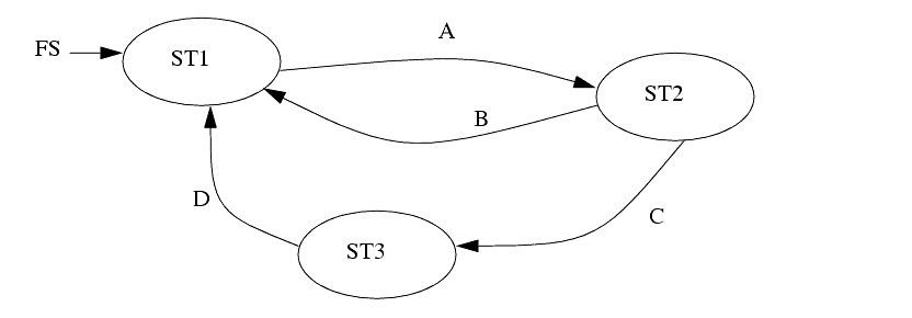
7. Write ladder logic to implement the state diagram below using state transition equations.
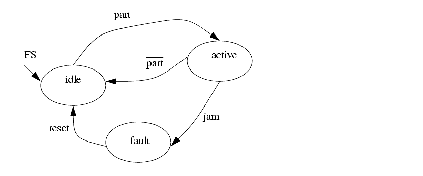
8. Convert the following state diagram to ladder logic using a) an equation based method, b) a method that is not based on equations.
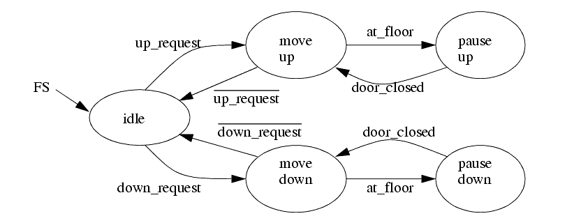
9. The state diagram below is for a simple elevator controller. a) Develop a ladder logic program that implements it with state transition equations. b) Develop the ladder logic using the block logic technique. c) Develop the ladder logic using the delayed update method.
10. Write ladder logic for the state diagram below a) using an equation based method. b) without using an equation based method.
11. For the state diagram for the traffic light example, add a 15 second green light timer and speed up signal for an emergency vehicle. A strobe light mounted on fire trucks will cause the lights to change so that the truck doesn't need to stop. Modify the state diagram to include this option. Implement the new state diagram with ladder logic.
12. Design a program with a state diagram for a hydraulic press that will advance when two palm buttons are pushed. Top and bottom limit switches are used to reverse the advance and stop after a retract. At any time the hands removed from the palm button will stop an advance and retract the press. Include start and stop buttons to put the press in and out of an active mode.
13. In dangerous processes it is common to use two palm buttons that require a operator to use both hands to start a process (this keeps hands out of presses, etc.). To develop this there are two inputs (P1 and P2) that must both be turned on within 0.25s of each other before a machine cycle may begin.
Develop ladder logic with a state diagram to control a process that has a start (START) and stop (STOP) button for the power. After the power is on the palm buttons (P1 and P2) may be used as described above to start a cycle. The cycle will consist of turning on an output (MOVE) for 2 seconds. After the press has been cycled 1000 times the press power should turn off and an output (LIGHT) should go on.
14. Use a state diagram to design a parking gate controller.
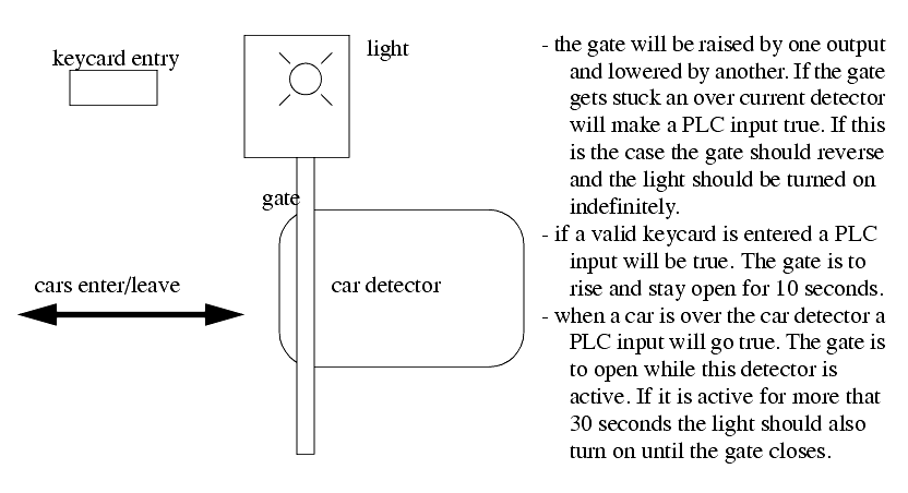
15. This morning you received a call from Mr. Ian M. Daasprate at the Old Fashioned Widget Company. In the past when they built a new machine they would used punched paper cards for control, but their supplier of punched paper readers went out of business in 1972 and they have decided to try using PLCs this time. He explains that the machine will dip wooden parts in varnish for 2 seconds, and then apply heat for 5 minutes to dry the coat, after this they are manually removed from the machine, and a new part is put in. They are also considering a premium line of parts that would call for a dip time of 30 seconds, and a drying time of 10 minutes. He then refers you to the project manager, Ann Nooyed.
You call Ann and she explains how the machine should operate. There should be start and stop buttons. The start button will be pressed when the new part has been loaded, and is ready to be coated. A light should be mounted to indicate when the machine is in operation. The part is mounted on a wheel that is rotated by a motor. To dip the part, the motor is turned on until a switch is closed. To remove the part from the dipping bath the motor is turned on until a second switch is closed. If the motor to rotate the wheel is on for more that 10 seconds before hitting a switch, the machine should be turned off, and a fault light turned on. The fault condition will be cleared by manually setting the machine back to its initial state, and hitting the start button twice. If the part has been dipped and dried properly, then a done light should be lit. To select a premium product you will use an input switch that needs to be pushed before the start button is pushed. She closes by saying she will be going on vacation and you need to have it done before she returns.
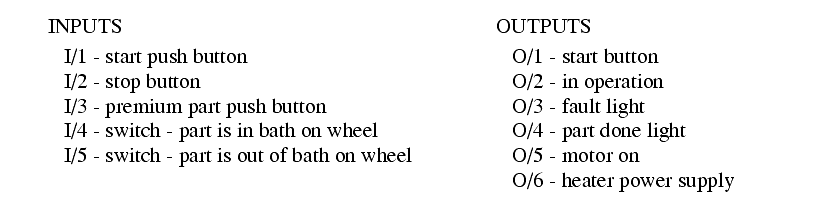
You hang up the phone and, after a bit of thought, decide to use the following outputs and inputs,
a) Draw a state diagram for the process.
b) List the variables needed to indicate when each state is on, and list any timers and counters used.
c) Write a Boolean expression for each transition in the state diagram.
d) Do a simple wiring diagram for the PLC.
e) Write the ladder logic for the state that involves moving the part into the dipping bath.
16. Design ladder logic with a state diagram for the following process description.
a) A toggle start switch (TS1) and a limit switch on a safety gate (LS1) must both be on before a solenoid (SOL1) can be energized to extend a stamping cylinder to the top of a part. Should a part detect sensor (PS1) also be considered? Explain your answer.
b) While the stamping solenoid is energized, it must remain energized until a limit switch (LS2) is activated. This second limit switch indicates the end of a stroke. At this point the solenoid should be de-energized, thus retracting the cylinder.
c) When the cylinder is fully retracted a limit switch (LS3) is activated. The cycle may not begin again until this limit switch is active. This is one way to ensure that a new part is present, is there another?
d) A cycle counter should also be included to allow counts of parts produced. When this value exceeds some variable amount (from 1 to 5000) the machine should shut down, and a job done light lit up.
e) A safety check should be included. If the cylinder solenoid has been on for more than 5 seconds, it suggests that the cylinder is jammed, or the machine has a fault. If this is the case the machine should be shut down, and a maintenance light turned on.
f) Implement the ladder diagram on a PLC in the laboratory.
g) Fully document the ladder logic and prepare a short report - This should be of use to another engineer that will be maintaining the system.
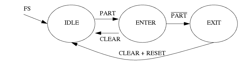
17. a) Write ladder logic to implement the state diagram below using the state transition equation method.
b) Write ladder logic to implement the state diagram below using the delayed update equation method.