6.7 PRACTICE PROBLEMS
������������
(Note: Problem solutions are available at http://sites.google.com/site/automatedmanufacturingsystems/)
1. Is the ladder logic in the figure below for an AND or an OR gate?
2. Draw a ladder diagram that will cause output D to go true when switch A and switch B are closed or when switch C is closed.
3. Draw a ladder diagram that will cause output D to be on when push button A is on, or either B or C are on.
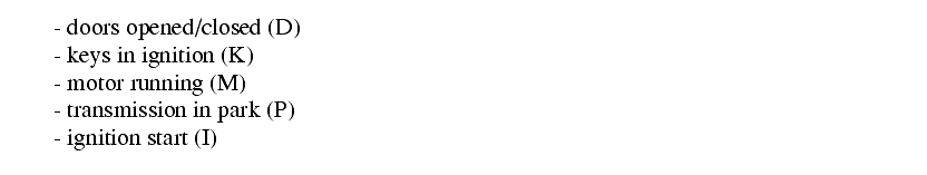
4. Design ladder logic for a car that considers the variables below to control the motor
M. Also add a second output that uses any outputs not used for motor control.
5. a) Explain why a stop button must be normally closed and a start button must be normally open.
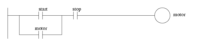
b) Consider a case where an input to a PLC is a normally closed stop button. The contact used in the ladder logic is normally open, as shown below. Why are they both not the same? (i.e., NC or NO)
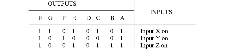
6. Make a simple ladder logic program that will turn on the outputs with the binary patterns when the corresponding buttons are pushed.
7. Convert the following Boolean equation to the simplest possible ladder logic.
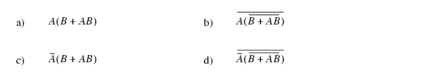
8. Simplify the following boolean equations.
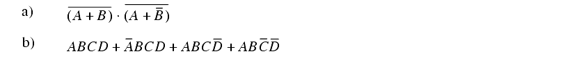
9. Simplify the following Boolean equations,
10. Simplify the Boolean expression below.
11. Given the Boolean expression a) draw a digital circuit and b) a ladder diagram (do not simplify), c) simplify the expression.
12. Simplify the following Boolean equation and write corresponding ladder logic.
13. For the following Boolean equation,
a) Write out the logic for the unsimplified equation.
b) Simplify the equation.
c) Write out the ladder logic for the simplified equation.
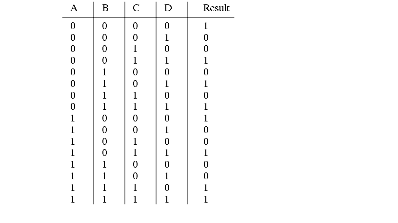
14. a) Write a Boolean equation for the following truth table. (Hint: do this by writing an expression for each line with a true output, and then ORing them together.)
b) Write the results in a) in a Boolean equation.
c) Simplify the Boolean equation in b)
15. Simplify the following Boolean equation, and create the simplest ladder logic.
16. Simplify the following boolean equation with Boolean algebra and write the corresponding ladder logic.
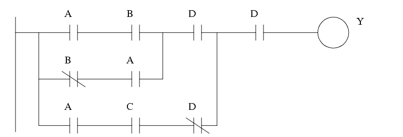
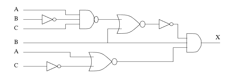
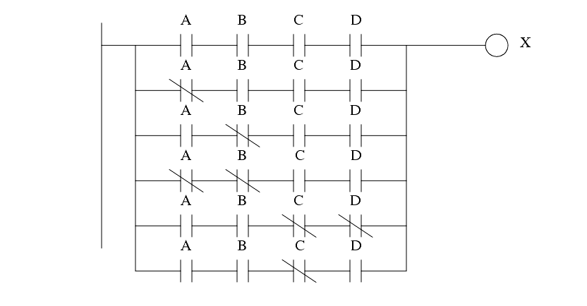
17. Convert the following ladder logic to a Boolean equation. Then simplify it, and convert it back to simpler ladder logic.
18. a) Develop the Boolean expression for the circuit below.
b) Simplify the Boolean expression.
c) Draw a simpler circuit for the equation in b).
19. Given a system that is described with the following equation,
a) Simplify the equation using Boolean Algebra.
b) Implement the original and then the simplified equation with a digital circuit.
c) Implement the original and then the simplified equation in ladder logic.
20. Simplify the following and implement the original and simplified equations with gates and ladder logic.
21. Convert the following ladder logic to a Boolean equation. Simplify the equation and convert it back to ladder logic.
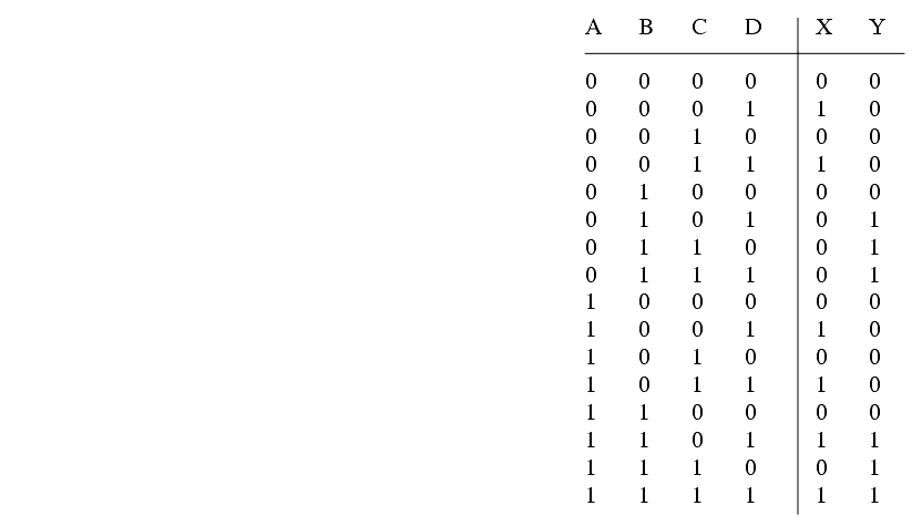
22. Use Boolean equations to develop simplified ladder logic for the following truth table where A, B, C and D are inputs, and X and Y are outputs.