|
|
|
|
|
|
|
|
12.3 NON-LINEAR ELEMENTS
������������If our models include a device that is non linear we will need to linearize the model before we can proceed.
A non-linear system can be approximated with a linear equation using the following method.
12.3.1 Time Variant
������������- system parameters vary as a function of time.

12.3.2 Switching
������������- system components turned on/off
- cables in tension/compression
- show an example where input conditions change
- give PWM (Pulse Width Modulation) example with ripple showing equivalent voltage. PWM is used to generate analog voltage equivalents. Show for a system with first order response with tau = 0.1s for a frequency of 1KHz, 10Hz and 1Hz. Point out the ripple and effective voltage.
- important to consider when doing system analysis
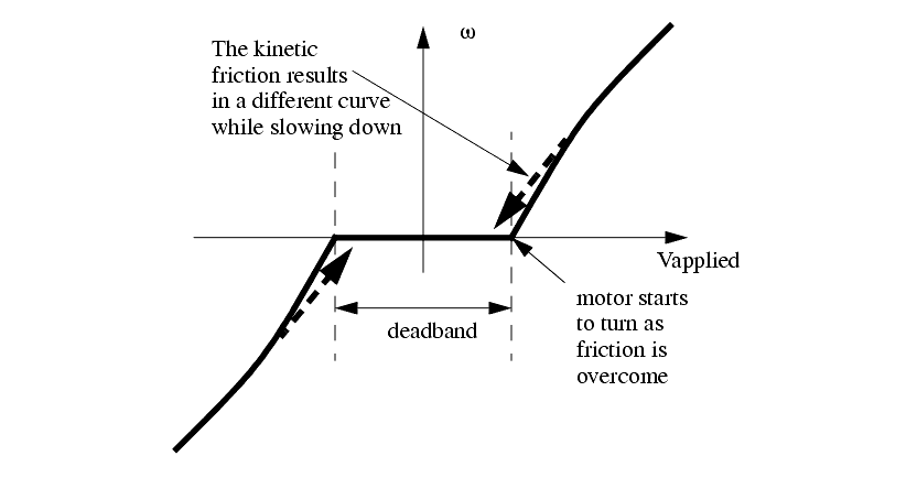
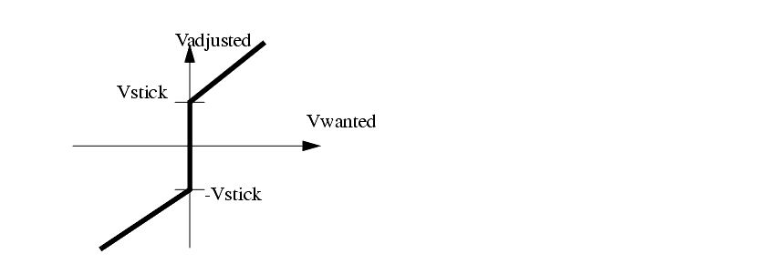
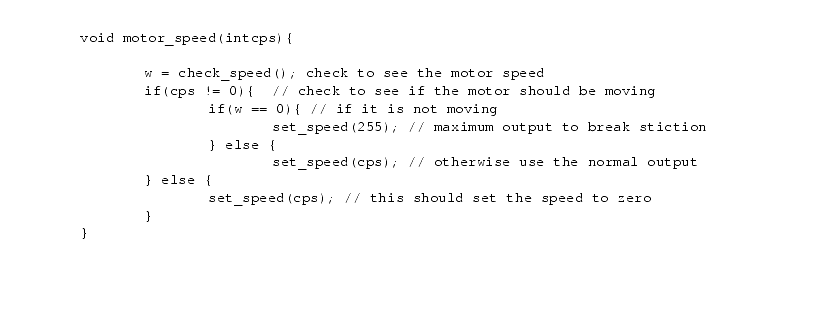
12.3.3 Deadband
������������- costs money to reduce friction, so it is better to compensate in software
- small actuation signals not large enough to overcome friction
- This effect is normally known as 'stiction', a combination of the words static and friction.
- Friction is common in less expensive motors, and when a motor is driving a mechanical system.
- In systems there are two type of friction that must be considered.
- The static friction, 'stiction', will prevent initial motion. If the systems breaks free and starts turning, the kinetic friction will provide a roughly constant friction resistance.
- relationship in figure below.
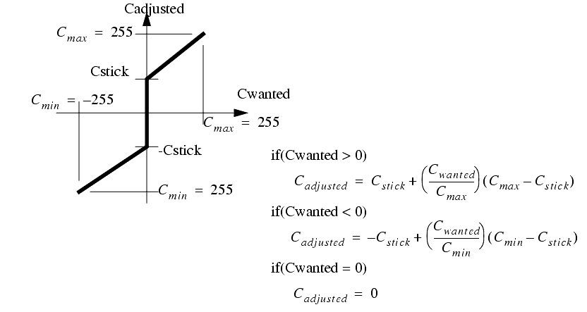
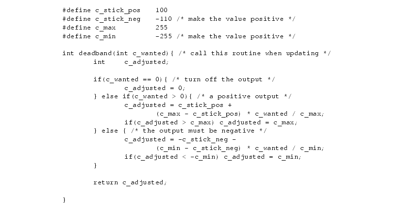
- the region where the applied voltage has no effect is called the deadband.
- deadband compensation as shown in figure below.
- equations for these are shown in figure
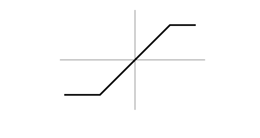
12.3.4 Saturation and Clipping
������������Some devices have natural maximum values, such as voltage or pressure limitations caused by a regulated supply.
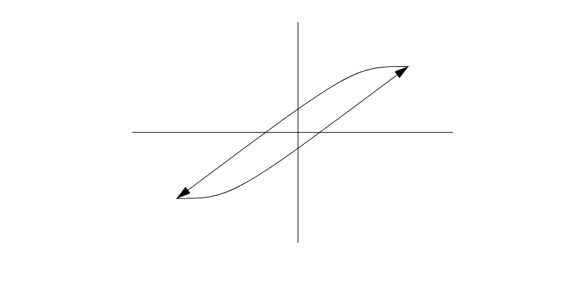
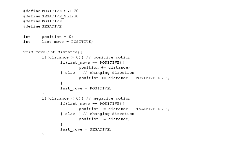
12.3.5 Hysteresis and Slip
������������- windup resulting from springiness and friction
- correct by tracking the previous motion direction and taking extra steps when reversing direction
- slip takeup can be done with the function below that adds a few steps when reversing direction.
12.3.6 Delays and Lags
������������Time delays are common in systems
In the simplest form this is a period of time between when an event occurs and when the effect occurs.
If an output delay is larger than the control system step time it may be necessary to predict future states and initiate outputs ahead of those.
If an input delay is larger than the control system it might be necessary to slow the control action, or build it into the control law.
Search for More: |

Custom Search
|
|