17.13 ASSIGNMENT PROBLEMS
������������
1. Prove the following relationships.
2. The applied force `f' is the input to the system, and the output is the displacement `x'.
b) What is the steady state response for an applied force F(t) = 10cos(t + 1) N ?
c) Give the transfer function if `x' is the input.
d) Find x(t), given F(t) = 10N for t >= 0 seconds using Laplace methods.
3. The following differential equation is supplied, with initial conditions.
a) Solve the differential equation using calculus techniques.
b) Write the equation in state variable form and solve it numerically.
c) Find the frequency response (gain and phase) for the transfer function using the phasor transform. Roughly sketch the bode plots.
d) Convert the differential equation to the Laplace domain, including initial conditions. Solve to find the time response.
4. Given the transfer functions and input functions, F, use Laplace transforms to find the output of the system as a function of time. Indicate the transient and steady state parts of the solution.
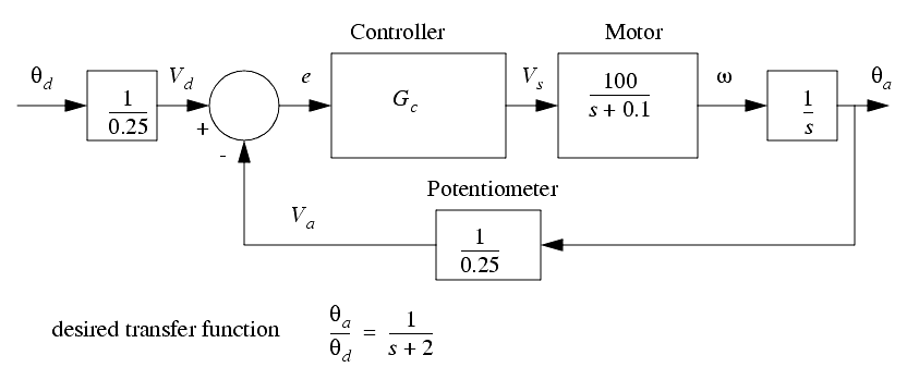
5. Select a controller transfer function, Gc, that will reduce the system to a first order system with a time constant of 0.5s, as shown below.
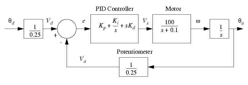
6. a) The block diagram below is for an angular positioning system. The setpoint is a desired angle, which is converted to a desired voltage. This is compared to a feedback voltage from a potentiometer. A PID controller is used to generate an output voltage to drive a DC motor. Simplify the block diagram.
b) Given the transfer function below, select values for Kp, Ki and Kd that will result in a second order response that has a damping factor of 0.125 and a natural frequency of 10rad/s. (Hint: eliminate Ki).
c) The function below has a step input of magnitude 1.0. Find the output as a function of time using numerical methods. Give the results in a table OR graph.
d) The function below has a step input of magnitude 1. Find the output as a function of time by integrating the differential equation (i.e., using the homogeneous and particular solutions).
e) The function below has a step input of magnitude 1. Find the output as a function of time using Laplace transforms.
f) Given the transfer function below; 1) apply a phasor/Fourier transform and express the gain and phase angle as a function of frequency, 2) calculate a set of values and present them in a table, 3) use the values calculated in step 4) to develop a frequency response plot on semi-log paper, 5) draw a straight line approximation of the Bode plot on semi-log paper.
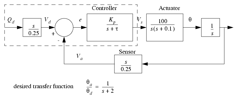
7. a) Simplify the block diagram as far as possible.
b) Given the transfer function below, select values for Kp and tau that will include a second order response that has a damping factor of 0.125 and a natural frequency of 10rad/s.
c) The function below has a step input of magnitude 1.0. Find the output as a function of time using numerical methods. Give the results in a table OR graph.
d) The function below has a step input of magnitude 1. Find the output as a function of time by integrating the differential equation (i.e., using the homogeneous and particular solutions).
e) The function below has a step input of magnitude 1. Find the output as a function of time using Laplace transforms.
f) Given the transfer function below; 1) apply a phasor/Fourier transform and express the gain and phase angle as a function of frequency, 2) calculate a set of values and present them in a table, 3) use the values calculated in step 4) to develop a frequency response plot on semi-log paper, 5) draw a straight line approximation of the Bode plot on semi-log paper.
g) Select a controller transfer function, Gc, that will reduce the system to a first order system with a time constant of 0.5s, as shown below.
8. Write a C program for an ATMega 32 microcontroller to implement the control system in the dashed line below with an update time of 10ms.
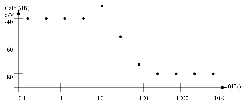
9. a) Given the experimental Bode (Frequency Response Function) plot below, find a transfer function to model a positioning system. The input is a voltage `V' and the output is a displacement `x'. (Hint: after calculating the function develop a Bode plot to verify the system performance.)
b) The transfer function found in step a) will be used for the positioning system in the block diagram below. Find the overall transfer function for the system.
c) Find a new controller transfer function (V/e) that would give the overall response below.
d) Write a subroutine that implements the control function (V/e) found in step c). (Hint: Convert it to state equations first.)
e) The controller function is replaced with the function below. Draw a Bode plot using the straight line approximation. Compare it to the Bode plot in part a).
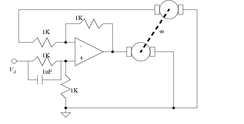
10. a) Develop differential and state equations describing the following system. The input is Vd and the output is the motor shaft speed. Assume all components are ideal. The motors are identical with a resistance of 20 ohms. With an input voltage of 5V the motors spin at 2000RPM, and have a time constant of 0.25s.
b) Find the system response to a unit step input explicitly (i.e. homogenous and particular).
c) Find the system response to a unit step input using Laplace transforms.
d) Solve the problem numerically and report the results using a table of values.
e) Use phasors to find the steady state output response to an input of,
11. a) Using Laplace transforms find the system response for the transfer function and input function (given as a function of time).
b) Use numerical methods to find the response of the system described with a transfer function. Report the results using a table of values.
c) Use phasors to find the steady state output response to the input given below.
12. Convert the following differential equations to physical systems. Show the method.
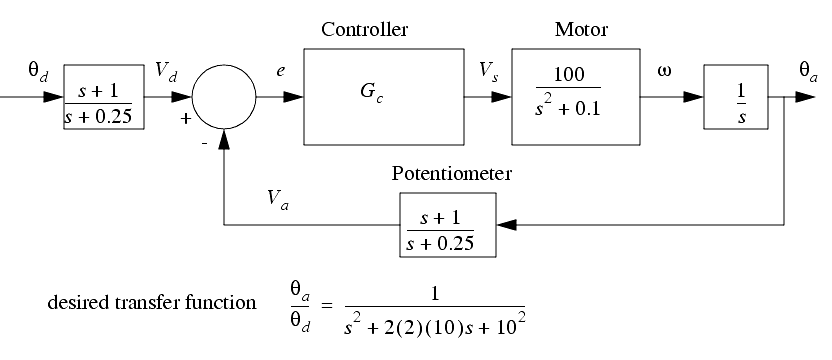
13. For the following control system select a controller transfer function, Gc, that will make the overall system performance match the desired transfer function.
14. Write a C program for an ATMega microcontroller to implement the control system in the dashed line below with an update time of 10ms.
15. A feedback control system is shown below. The system incorporates a PID controller. The closed loop transfer function is given.
a) Develop the transfer function for the system.
b) Select controller values that will result in a response that includes a natural frequency of 2 rad/sec and damping factor of 0.5. Verify that the controller will be stable.
c) If the values of Kp = Ki = Kd = 1 find the response to a unit ramp input as a function of time using LaPlace Transforms.
d) Find the response in part c) using numerical methods.
e) Find the system response to an input of X = 5sin(100t + 1)
f) If the input X is a trapezoidal motion profile with an acceleration time of 2 seconds, and a maximum velocity of 5, what would the response Y look like.
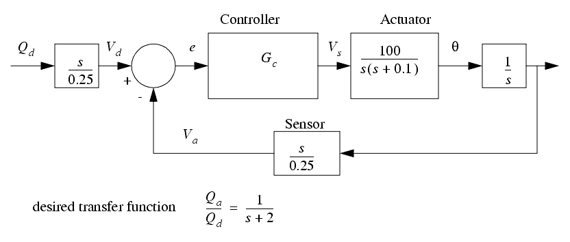
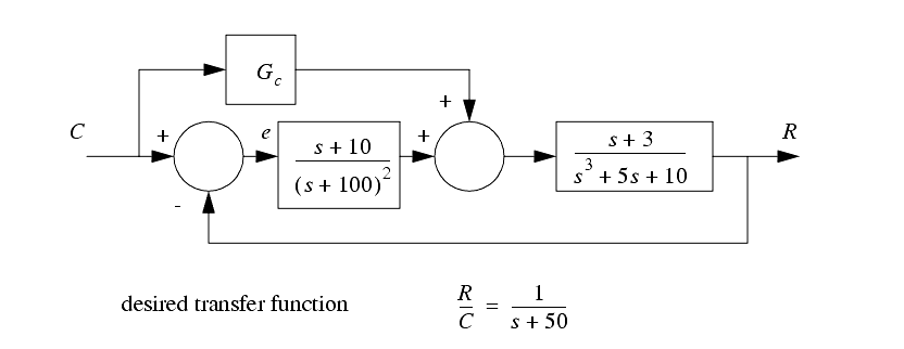
16. For the following control system select a controller transfer function, Gc, that will make the overall system performance match the desired transfer function.
17. A feedback control system is shown below. The system incorporates a PID controller. The closed loop transfer function is given.
a) Develop the transfer function for the system.
b) Select controller values that will result in a response that includes a natural frequency of 2 rad/sec and damping factor of 0.5. Verify that the controller will be stable.
c) If the values of K1 = K2= 1 find the response to a unit ramp input as a function of time using LaPlace Transforms.
d) Find the response in part c) using numerical methods.
e) Find the system response to an input of X = 5sin(10t + 1) using phasor transforms.
f) If the input X is a trapezoidal motion profile with an acceleration time of 2 seconds, and a maximum velocity of 5, calculate the response Y.


