15.1 SEIKO RT 3000 MANIPULATOR
������������
In general
Maximum payload 5kg (11 lb)
Repeatability (based on constant temp., load, speed) +/-0.025mm (+/- 0.001 in.)
Operating Temperature 0C to 40C (32F to 104F)
Humidity (based on constant temp. load, speed) 20% to 90%
Power Requirements 200-240 VAC
A-axis
Z-axis
Resolution 0.0005 in (0.012mm)
max. speed 14 in/sec (360 mm/sec)
max. force 23.3-35.2 lbs (10.6-16.0 kg)
R-axis
Resolution 0.001 in (0.025mm)
max. speed 29.5 in/sec (750 mm/sec)
T-axis
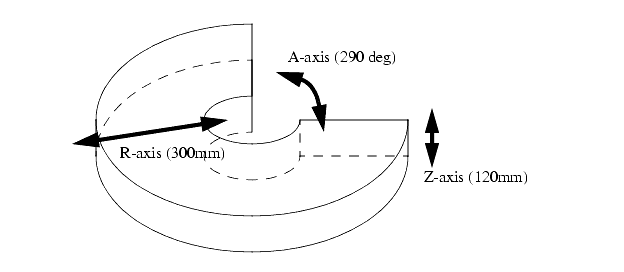
The workspace is pictured below,
15.1.1 DARL Programs
������������
All DARL comments follow ' at any position on a line.
Statements are ended with a colon, and as long as colons are used, more than one statement can be used on a line.
Line numbering is required for DARL programs.
Dimensions are given in millimeters in the programs.
Commas and spaces are treated as equivalent.
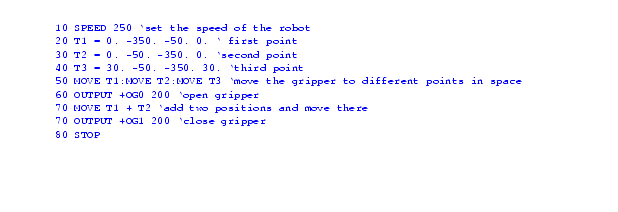
A sample program is given below with comments for explanation,
15.1.1.1 - Language Examples
������������
First, points can be defined in programs, they can also be defined by moving the robot to the location and storing the value. This allows the robot to accurately find points without measuring. It also means that points location values don't need to appear in programs, they are stored in memory.
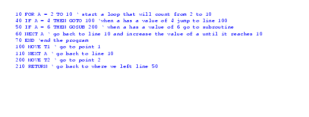
A example that uses for-next, if-then, goto and gosub-return commands is shown below. These commands are very standard in their use.
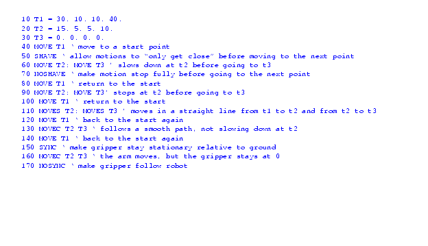
A example that uses motion is shown below. The `move' command causes a motion to another point by only turning the needed joints. `moves' causes a more complex motion resulting in a straight line tool motion between points. `movec' allows a circular interpolation dictated by three points (the start, and the two given). The shave command forces the robot to fully complete a motion and stop before going to the next point. The sync command will move the robot, but keep the gripper in the original position relative to the real world.
|
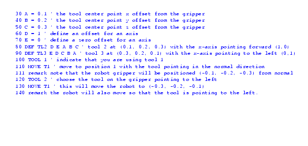
A example that defines tool location offsets is shown below. This is particularly useful for a robot that has more than one tool attached. The normal tool location is on the end of the arm. With multiple tools attached we will have multiple tool center points. We can have a tool definition for each one of these. Note that the x-axis is the normal forward for the tool. The tool axis can only be changed in the x-y plane (or the plane perpendicular to the gripper rotation).
|
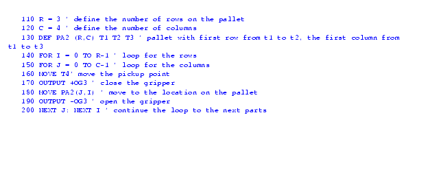
A example that uses pallet commands is shown below. Basically a pallet allows us to create an array of points (it does the calculations). We can then give a location on a pallet and move to that point. The basic pallet definition requires that we indicate the number of rows and columns. We also need to define the physical locations of the rows and columns. We do this by giving an origin point, and then defining where the first row and column end. To use the pallet location we can simply refer to the pallet location index.
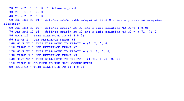
A example that defines and uses new frames is shown below. We define a new frame of reference by using points. The first point becomes the new origin. The second point determines where the new x-axis points. The z-axis remains vertical, and the y-axis is shifted appropriately.
A example that uses simple inputs and outputs is shown below. Note that there are two connectors for I/O. The main or `E'xternal connector is on the main controller box. The other I/O lines are on the `G'ripper. We can check the states of inputs and set the states of outputs. The `+' sign indicates inputs/outputs high (5v) and the `-' sign indicates low (0V). The ranges for input points are ie0-ie15, ig0-ig7, and for output points oe0-15, og0-7. The search command allows us to move the robot until an input is activated. This is useful when attempting to find a part by touching it.
15.1.1.2 - Commands Summary
������������
A summary of the commands is given below,

