26. Composite Manufacturing
• Each material has desirable properties, but in most situations the perfect material is never found.
• Composites allow mixing of materials to get the best of both.
• BASIC PRINCIPLE: different types of materials are blended together. The materials are often quite different in terms of properties, and the results are a new material that has many of the desired properties of each material.
• Examples
clay bricks with embedded straw
reinforced concrete
samurai swords with steel/iron alternation of layers
steel belted radials
graphite tennis racquets
fishing poles
• for reinforced plastic composites, 2,500,000,000 pounds of plastic based composites were shipped in a wide variety of products in the mid 80’s
26.1 Fiber Reinforced Plastics (FRP)
• Typical properties that may be desired are,
light weight
stiffness
strength
heat resistant
impact resistance
electrical conductivity
wear resistance
corrosion resistance
low cost
• Some notable applications are,
Automotive: engine blocks, push rods, frames, piston rods, etc.
Electrical: motor brushes, cable electrical contacts, etc
Medical: prostheses, wheel chairs, orthofies, etc.
Sports equipment: tennis racquets, ski poles, skis, fishing rods, golf clubs, bicycle frames, motorcycle frames
Textile industry: shuttles
etc.
• Some advantages are,
composites provide a maximum tensile strength to density ration approximately 4 to 6 times greater than steel or aluminum
can provide a maximum material stiffness to density ratio of 3.5 to 5 times that of aluminum or steel
high fatigue endurance limits
absorb higher impact energies
material properties can be strengthened where required
corrosion potential is reduced.
joints and fasteners are eliminated or simplified
• Some disadvantages are,
If either material is susceptible to local solvents, the composite cannot be used
materials can be expensive
design and fabrication techniques are not well explored and developed.
• fibers are often graphite, glass, aramid, etc.
• the fibers are supported in the matrix, quite often a polymer, epoxy, etc.
• The polymer matrix is often referred to as the resin
• The matrix transfers the load to the reinforcement fibers, and it protects the fibers from environmental effects.
• Resins tend to be thermosetting, or thermoplastic
Thermoplastics: melt, and harden with temperature
Thermosets: undergo a chemical change, and cannot be “recast”. The setting is often heat activated.
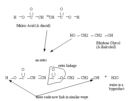
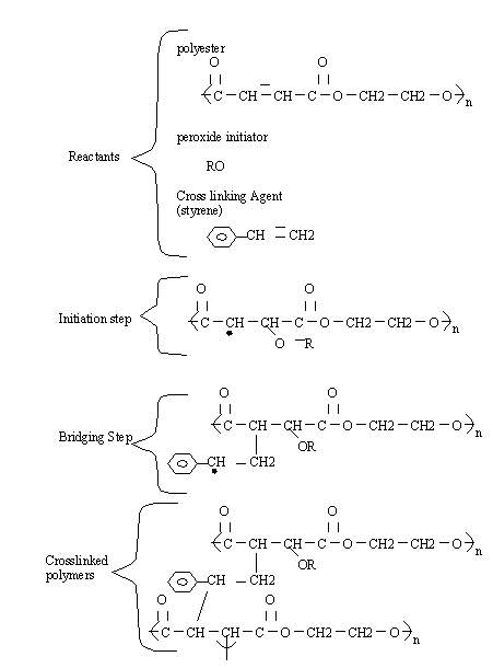
• Polyester resins are quite common. The process often begins with molecules like a dialcohol, and diacid. These then cure into a solid polymer.
• These reactions create very long chains of polymers in a sort of gel, but the next step involves cross-linking them to make things stiff
• Various chemical reactions, and physical properties can be altered by changing the chemicals above. Rates of reaction can be accelerated with higher temperatures.
• The initiator is often stored separately from the other reactants to prevent cross linking before use. This may happen spontaneously, and so the chemicals should be discarded if too old.
• Epoxies can also be used, they can be expensive and toxic, but they generally have better overall performance than polyesters.
• Other general categories are,
Polymides and Polybenzimidazoles
Phenolics and Carbon matrices
Thermoplastics
Ceramic matrices
Metal matrices
• Polyesters are generally inexpensive, and can be modified for other properties.
• Epoxies are used when the matrix must have good adhesion, strength and corrosion resistance in severe environments.
• Polyimides are used for high temperature applications (up to 600 F/316 C) but are difficult to process
• Phenolics are good for thermal insulation
• Ceramics are used for high temperature, low strength applications.
• Reinforcements in materials can be
fibers: long directional filaments
particles: small non-directional chunks
whiskers: small directional filaments
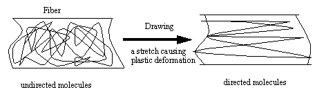
• Fibers have very long lengths with respect to the surrounding material, and tend to have a significantly higher strength along their length.
• Fibers are often drawn to align the molecules along the fiber length
• Glass fibers are basically made by,
1. Mixing silica sand, limestone, boric acid, and other minor ingredients
2. The mixture is heated until it melts at about 2300F/1260C
3. Letting the molten glass flow through fine holes (in a platinum plate)
4. The glass strands are cooled, gathered and wound. (protective coatings may be added.)
5. The fibers are drawn to increase the directional strength.
6. The fibers are woven into various forms for use in composites
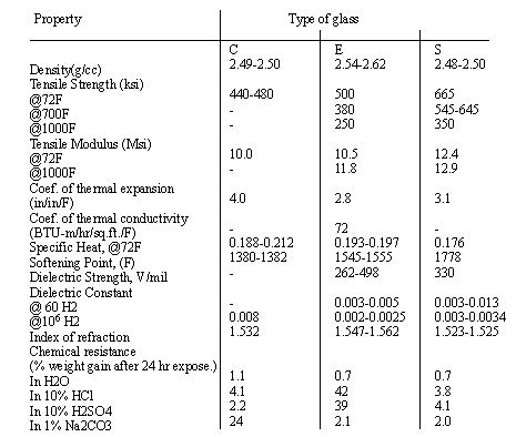
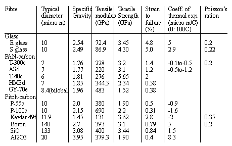
• There are three common glass types used, E, S, C
E: less expensive
S: 40% stronger than E, and more resistant to temperature
C: well suited to corrosive environments
• Carbon Fibers are among the highest strength and modulus materials known.
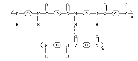
• Aramids (Kevlar) fibers are shown below. These do not need to be drawn as they are already in the correct orientation when produced.
• aramid fibers come in bundles of 134 to 10,000 filaments
• kevlar properties are,
• Other popular fiber types are Boron, Silicon, Carbide, Alumina, etc.
• The fibers come in a variety of configurations,
Filament: a single fiber
Strand: Could refer to a single fiber, or an untwisted bundle of filaments
Tow: A bundle of untwisted fibers, often a predetermined number.
Yarn: A twisted tow
Roving: A number of yarns pulled together without twisting
Tape: a thin and wide run of parallel fibers
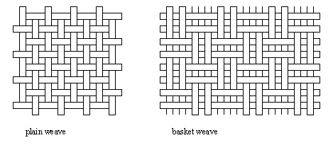
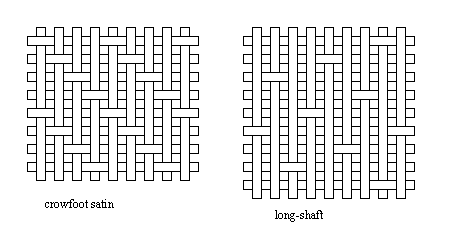
Woven fabric: yarns and tows are interlaced to create flat cloth
Braids: yarns and tows are woven into tubular shapes
Mat: chopped fibers create an undirected pattern in a flat cloth. A binder holds the fibers together.
• There are different weave types used, these provide different workabilities, air removal, distortions, etc.
• weaves can be made from single fiber types, or combinations
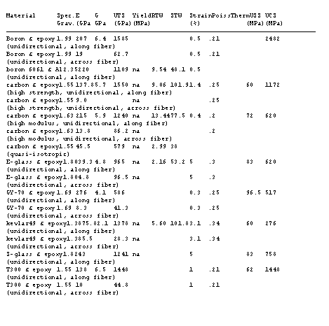
• The relative material properties for composites are seen in the figures below
RTW: Rigidity to weight
STW: strength to weight
Strain: failure strain
UTS: ultimate tensile strength
Yield: yield strength
USS: Ultimate shear strength
UCS: Ultimate compressive strength
• Composites are sensitive to temperature and humidity during curing.
• When dealing with cyclic loading over a million cycles
Aluminum and steel design with 0.1 of the normal yield strength
Composites design with 0.5 of normal yield strength
• Composites in general are very easy to shape, and form, this is not always possible with other high strength materials
• Composites are anisotropic and have good strength along the fibre length, but reduced strength across the fiber axis.
• Elongation of composites is typically linear up to fracture at 1% to 2% elongation
26.2 Composite Manufacturing
• The basic process involves,
1. creation of a mold/form
2. Preimpregnation of the fibers (or the later addition of resin)
3. Applying fibers to the mold or form
4. Applying resin if not a prepreg
5. curing of composite in oven (possibly an autoclave)
6. finishing to remove excess, etc.
26.2.1 Manual Layup
• Commonly used for polyester and fiberglass
• Wet Layup
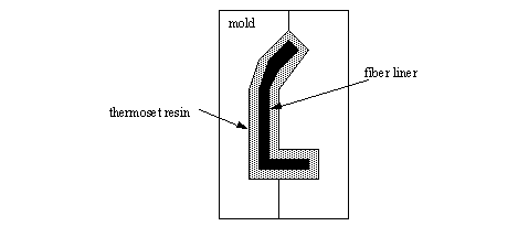
the dry fabric, or mat is laid in the mold. Resin is then poured on and then rolled or squeegeed evenly over the surface, with attention to removal or air pockets. This is done in layers until the part is done. Fabric can be prewet before laying to allow better fiber/matrix ration control. A parting agent, such as silicone is applied to the mold to allow easy removal or the finished part. Vacuum bags can be used to: remove trapped air/voids trapped in the matrix that weakens the composite; pull the fabric to the mold; compress the composite layers.
molds are often made from wood, plater, plastic, composites
the surface of the part that touches the mold will be the good surface (take a very good opposite of the mold). The back surface will be rough.
Curing is often done at room temperature, but hot air blowers and infrared lamps can accelerate the process.
• Advantages of wet layup
tooling can be made of any material that can withstand a small pressure.
tooling can be easily changed.
expensive equipment is not required, but a vacuum pump is often use for epoxies, and some polyesters.
curing ovens are not required.
highly skilled workers are not required.
• Disadvantages of wet layup,
condensation type cross linking (of the polymer matrix) cannot be used because pressure would be required to remove entrapped condensate.
the techniques lead to a great deal of variation between each part.
resin content tends to be high because pressure compaction is not used.
voids are common in the matrix.
the strength of the materials tends to be poorer compared to other composite methods. This is in part because the fabrics have a tight weave and are hard to impregnate with resin.
resin might run when on non-horizontal surfaces, causing pooling of resign. In these cases higher viscosity resins are often used.
there is more shrinkage in volumes with higher resin contents.
only one finished surface is possible.
• Prepreg layup
the fibres are purchased with resin already mixed. They commonly come in various widths (3 to 72 inches) and have a leathery feel. They are slightly tacky so that they will stick when formed. (The resins can be thermoplastic or thermoset). After layup the part is vacuum bagged and oven cured. The prepreg materials degrade over time, and should be kept in cool environments.
• Advantages of prepreg layup,
because the resins are mixed by the manufacturer, the ratio of components is more closely controlled. The manufacturer also ensures better distribution of the resin in the cloth. The manufacturer also performs most of the operations normally hazardous to health.
Automated machines can also be used to overcome efficiency problems
typically this method gives better physical properties than the wet layup method
• Disadvantages of Prepreg layup,
vacuum bagging is required to properly consolidate layers, and remove voids.
expensive curing ovens must typically be used.
the vacuum bagging procedure leaves room for more scrapped parts.
it can be difficult to bag complex parts.
• During layup the fiber orientations are often arranged at multiple angles.
e.g. 90, 45, -45, -45, 90, 0 degrees
• Typical fiber content in the matrix is 60%
• Typical desired maximum of air/voids in the matrix is 0.5%. There is about a 7% loss of strength for every 1% of voids, up to 4%.
• Disadvantages of manual layup methods,
these methods tend to be slow compared to automated methods
surface finishes are not the best possible
long cure cycles are required
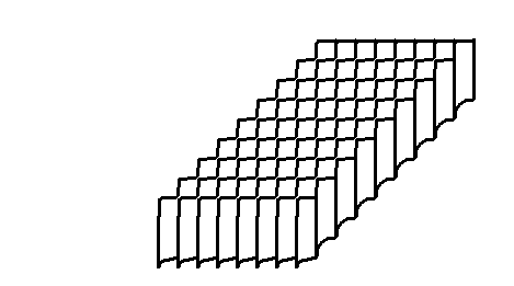
26.2.2 Automated Tape Lamination
• Basically does layup with automated machine.
• An overhead gantry moves a tape application head across the mold, and up inclined faces to apply a prepreg tape, 3” width is typical. Cutting and trimming is done automatically.
• NC programs direct the tape layup, often in geodesic paths.
• This methods saves time, increases part consistency and precision, but requires programming and is unable to handle some complicated parts.
26.2.3 Cutting of Composites
• Cuts can be made with common utility knives, carbide disc cutters (pizza cutters), etc.
• Multiple sheets can be cut at the same time, reducing cost and increasing consistency.
• more advanced cutters use ultrasonics, water jets (care is required not to wet the materials), die cutting, laser cutting, etc.
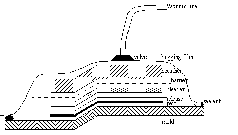
26.2.4 Vacuum Bags
• Application of a vacuum to the resin helps eliminate residual materials/gas trapped in the uncured resin.
air pockets
solvents
low molecular weight resin components
etc.
• Basic steps are,
1. Coat the mold with a mold release agent. This allows the part to easily separate later.
2. Remove prepreg materials from the freezer. Allow the materials to warm to room temperature to reduce condensation: this would contaminate the materials.
3. Build up the layers of the part. Inserts, ribs, etc. may be inserted at this stage.
4. Put a layer of release film on the part. This allows resin to flow out under vacuum, and leaves a good surface for subsequent composite layers to bond to.
5. Add the bleeder layer. This layer will soak up excess resin. It is typically a mat of cotton, polyester felt, or fiberglass (with teflon coat), etc.
6. (Optional) Add a layer of barrier to prevent resin movement to the vacuum valve, but allow air movement. A resin trap should be used in the vacuum system if this step is omitted.
7. (Optional) Add a layer of breather material. This will act as a buffer between the wrinkles in the bag, and the part surface. It also allows better distribution of the vacuum.
8. Apply a sealant around the edges of the part. This can be a tape.
9. Insert thermocouples and any other monitoring devices into the assembly, and ensure that they will not allow air leaks at the sealant. These will be used to monitor cure rates, and control oven temperatures.
10. Put the vacuum bag over the part, and seal at the edges. A typical material is nylon. The vacuum is then applied, and possibly a curing oven is used to accelerate curing.
26.2.5 Autoclaves
• Basically an oven that also uses pressure.
• The part is placed in the pressure vessel, and heated, pressure is applied simultaneously. Vacuum bagging can be used to increase the heating effects.
• The heat accelerates the curing of the thermosets, or melting of the thermoplastic resins.
• The pressure helps bond layers, and remove more voids in the matrix.
• Inert gases are often injected to prevent fires.
• Although autoclaves are expensive, they produce better parts, and can process many parts at the same time.
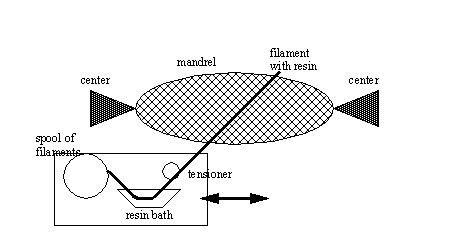
26.2.6 Filament Winding
• Basic (Typical) Process: A tape of resin impregnated fibres is wrapped over a rotating mandrel to form a part. These windings can be helical or hooped. This continues until the part is thick enough. There are also processes that use dry fibres with resin application later, or prepregs are used.
• Parts vary in size from 1” to 20’
• mixtures of hoop/helical layers, and layers of different materials allow higher strengths in various direction, and resistance to impact damages.
• geodesic paths are commonly preferred with this approach.
• winding speeds are typically 100 m/min.
• typical winding tensions are about 0.1 to 0.5 kg.
• to remove the mandrel, the ends of the parts are cut off when appropriate, or a collapsible mandrel is used when the parts must remain intact. (one way to do this is with low melt temperature alloys).
• entire parts on mandrels can be cured in autoclaves when desired. A rotating mandrel will help reduce the resin flow effects caused by gravity.
• inflatable mandrels can also be used to produce pretensioned parts that are designed for high pressure applications, or parts that need a liner, and they can be easily removed.
• this method is well suited to round parts, or parts undergoing high hoop stresses.
• advantages
can handle a wide variety of part sizes
parts can be made with strength in several different directions
high percentage of material usage
forming after winding will allow non-cylindrical shapes to be made
flexible mandrels can be left in as tank liners
reinforcement panels, and fittings can be inserted during winding
parts with high pressure ratings can be made
• disadvantages,
viscosity and pot life of resin must be carefully chosen
NC programming can be difficult
Some shapes can’t be made with filament winding
Factors such as filament tension must be controlled
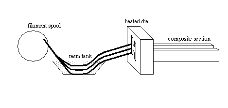
26.2.7 Pultrusion
• Basic principle: fibers are brought together over rollers, dipped in resin and drawn through a heated die. A continuous cross section composite part emerges on the other side.
• Some points of interest include,
Hollow parts can be made using a mandrel that extends out the exit side of the die.
Variable cross section parts are possible using dies with sliding parts.
Two main types of dies are used, fixed and floating
Fixed dies can generate large forces to wet fiber
Floating dies require an external power source to create the hydraulic forces in the resin.
Multiple dies are used when curing is to be done by the heated dies.
Up to 95% utilization of materials (75% for layup).
Most fibers are suitable for this process
Resins must be fast curing because of process speeds.
Rollers are used to ensure proper resin impregnation of the fiber
Resins can also be introduced in the die if perforated metal surfaces are used. Prepreg parts are also used.
Material forms can also be used at the inlet to the die when materials such as mats, weaves, or stitched material is used.
For curing, tunnel ovens can be used. After the part is formed and gelled in the die, it emerges, enters a tunnel oven where curing is completed.
Another method is the process runs intermittently with sections emerging from the die, and the pull is stopped, split dies are brought up to the sections to cure it, they then retract, and the pull continues. (Typical lengths for curing are 6” to 24”)
• Typical parameters for,
speeds are 0.6 to 1 m/min
thickness are 1 to 76 mm
diameters are 25mm to 5m
• double clamps, or belts/chains can be used to pull the part through. The best designs allow for continuous operation for production.
• diamond or carbide saws are used to cut sections of the final part. The saw is designed to track the part as it moves.
• these parts have good axial properties
• Advantages,
good material usage compared to layup
high throughput
higher resin contents are possible
• Disadvantages,
part cross section should be uniform
fiber and resin might accumulate at the die opening, leading to increased friction causing jamming, and breakage.
when excess resin is used, part strength will decrease
void can result if the die does not conform well to the fibers being pulled
quick curing systems decrease strength
26.2.8 Resin-Transfer Molding (RTM)
• Basic principle: A mold is filled with fiber, it is closed and resin is injected. The mold is often in vacuum before injection. The pressure of injection wets the fibers.
• This process was used to make car body panels.
• The fiber in the mold can be any that holds its shape during the injection. Layers are often stitched, and bonded.
• Inserts/ribs/etc can easily be put into the mold before it is closed.
• most resins can be used, but low viscosities are useful.
• Advantages,
Very large and complex shapes can be made efficiently and inexpensively
production times are very short compared to layup
low clamping pressures
better surface definition than layup
inserts and special reinforcements are easily added
operators may be unskilled
A large number of mold materials may be used
part consistency is good
worker exposure to toxic chemicals is reduced
• Disadvantages,
Mold design is complex
material properties are good, but not optimal
resin to fiber ratio is hard to control, and will vary in areas such as corners
reinforcement may move during injection, causing problems
26.2.9 General Information
• Resin curing is best done through slow heating, rapid heating will reduce final strength of the part.
• The composite sheets may be strong, but in thin layers they are less capable of resisting bending moments. To overcome this a honeycomb core can be used inside to increase bending resistance. Typical core materials are,
PVC foams
aluminum honeycombs
paper honeycombs
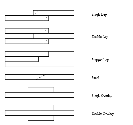
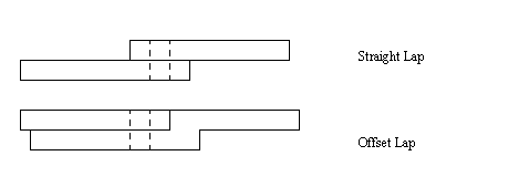
• Joining of composites may be done using adhesives,
• There are a wide variety of techniques for joining composites, beyond those shown here. Most attempt to maximize contact areas by using tongues, oblique planes, etc.
• Composites may also be joined with mechanical fasteners, (NOTE: use drilled holes, instead of trying to warp fiber about hole: this leads to resin rich areas)
26.2.10 References
Mallick, P. R., Fiber-Reinforced Composites; materials, manufacturing and design, Mercel-Dekker Inc., New York, 1988.
Mallick, P. K., and Newman, S., Composite Materials Technology, Hanser Publishers, New York, 1990.
Schwartz, M. M., Fabrication of Composite Materials, American Society for Metals, Metals Park, Ohio, 1985.
Strong, A. B., Fundamentals of Composite Manufacturing, Society of Manufacturing Engineers, Dearborn Michigan, 1989.
26.2.11 Problems
Problem 26.1 a) List at least 5 advantages of composite materials.
b) List at least 3 disadvantages of composite materials.
Problem 26.2 For thermoset polymers, what effects does cross-linking generally have on the material properties?
Problem 26.3 Which type of glass is good for applications that require,
Problem 26.4 a) Low cost?
b) Operate at high temperatures?
c) Are resistant to corrosion?
Problem 26.5 a) List 6 different forms (other than single filaments) that composite fibers may be purchased in.
b) What form of composite fibers are best used for pultrusion?
Problem 26.6 If you were making boat hulls with pre-preg composite fiber and large molds, what steps would be followed?
Problem 26.7 Indicate if the following parts are best made with pultrusion/filament winding/resin transfer molding.
rocket engine tanks
car body panels
airplane fuselage
a mast for a sail boat
Problem 26.8 A composite section has a honeycomb core 1” thick and can withstand a maximum bending moment of 10KN. How much thicker/thinner would the honeycomb have to be to withstand 1KN?
Problem 26.9 TRUE / FALSE: Multi-directional fibers can be used with stereolithography to increase part strength.
Problem 26.10 What are the major factors that weaken composites? Explain the effect of each.
Problem 26.11 Describe the difference between alloys and composites.
Problem 26.12 Describe the properties of the matrix and fiber materials, and then describe why their combinations is so desirable.
Problem 26.13 What properties does a honeycomb core contribute to a composite part?
Problem 26.14 List 10 products that you have purchased or used that are made of composite materials.
Problem 26.15 What are the advantages and disadvantages of composite materials. What design considerations can be used to overcome the disadvantages?
Problem 26.16 A composite has more than one type of fiber. Why would this be desirable?
Problem 26.17 A part is made of a composite material that is 40% fibers (by area) with a Young’s modulus of 300 GPa, and a matrix of 60 Gpa. The UTS of the fibers is 2000 GPa and 100 MPa for the matrix. If the total cross sectional area of the part is 2cm by 0.2cm, what is the effective stiffness and failure load?
Problem 26.18 Calculate the percentage increase in strength of nylon when e-glass fibers are added.
Problem 26.19 List 5 parts that benefit from the anisotropic properties of composites. Explain why.
Problem 26.20 Corrugated cardboard and composite honeycomb have similar construction. What are the similarities and differences in behavior?
Problem 26.21 List 8 different types of composite manufacturing processes and give an example of a part they are well suited to.
Problem 26.22 Composite materials typically cost more than metals. why are they preferred?
Problem 26.23 List 10 factors determine the strength of a composite materials and parts?