3. Basic Cutting Tools
3.1 Cutting Speeds, Feeds, Tools, and Times
• Cutting is a balance between a number of factors,
cutting slowly will add costly time to manufacturing operations.
cutting faster will lead to decreased tool life, and extra time will be required to repair tools.
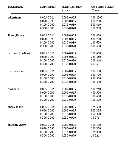
• Some reasonable speeds and feeds for a single cutting point tool are given below [Krar],
3.2 High Speed Machining
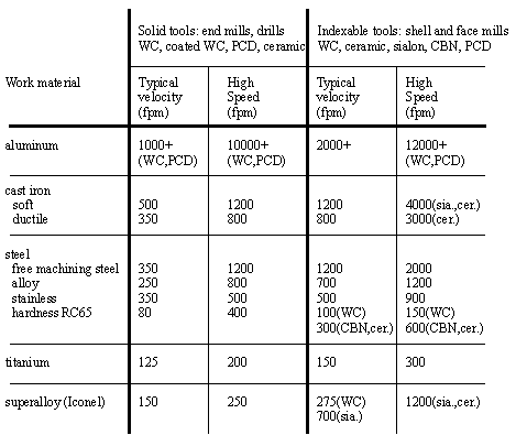
• Usually spindle speeds above 10000 RPM, but this is highly relative to the cutting tool and work.
• The cutting velocity is higher, but the feed/depth of the cut is reduced, the resulting mrr is still higher.
• Higher spindle speeds call for new low inertia spindle, and tolerances as well. Small tolerance problems can result in unacceptable vibrations at these speeds.
• The table below is an example of some cutting speeds [Ashley, 1995]
3.3 References
3.1 Ashley, S., “High Speed Machining Goes Mainstream”, Mechanical Engineering, published by the ASME, May 1995, pp. 56-61.
3.4 Cutting Theory
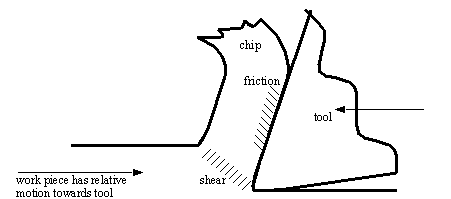
• When we cut metal, the severed pieces are cast off, these are referred to as chips.
3.4.1 Chip Formation
• There are three types of chips that are commonly produced in cutting,
discontinuous chips
continuous chips
continuous with built up edge
• A discontinuous chip comes off as small chunks or particles. When we get this chip it may indicate,
brittle work material
small rake angles
coarse feeds and low speeds
• A continuous chip looks like a long ribbon with a smooth shining surface. This chip type may indicate,
ductile work materials
large rake angles
fine feeds and high speeds
use of coolant and good chip flow
• Continuous chips with a built up edge still look like a long ribbon, but the surface is no longer smooth and shining. This type of chip tends to indicate,
high friction between work and tool causes high temperatures that will occasionally weld the chip to the tool. This will break free, but the effects is a rough cutting action.
• Continuous chips, and subsequently continuous cutting action is generally desired.
3.5 The Mechanics of Cutting
• Assuming that the cutting action is continuous we can develop a continuous model of cutting conditions.
• Orthogonal Cutting: assumes that the cutting edge of the tool is set in a position that is perpendicular to the direction of relative work or tool motion. This allows us to deal with forces that act only in one plane.
• We can obtain orthogonal cutting by turning a thin walled tube, and setting the lath bit cutting edge perpendicular to the tube axis.
• Next, we can begin to consider cutting forces, chip thicknesses, etc.
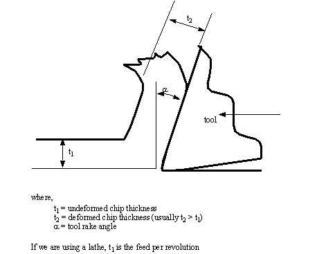
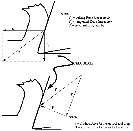
• First, consider the physical geometry of cutting,
• Next, we assume that we are also measuring two perpendicular cutting forces that are horizontal, and perpendicular to the figure above. This then allows us to examine specific forces involved with the cutting. The cutting forces in the figure below (Fc and Ft) are measured using a tool force dynamometer mounted on the lathe.
3.5.1 Force Calculations
• The forces and angles involved in cutting are drawn below,
• Having seen the vector based determination of the cutting forces, we can now look at equivalent calculations
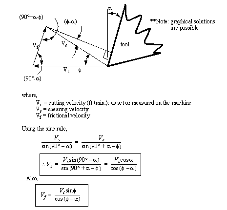
• The velocities are also important, and can be calculated for later use in power calculations. The Velocity diagram below can also be drawn to find cutting velocities.
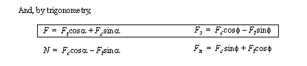
• A final note of interest to readers not completely familiar with vectors, the forces Fc and Ft, are used to find R, from that two other sets of equivalent forces are found.,
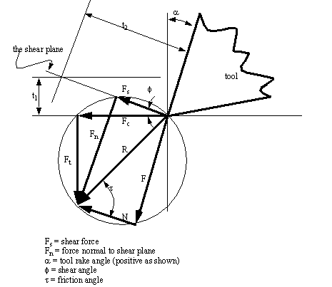
3.5.1.1 - Merchant’s Force Circle With Drafting
• Merchant’s Force Circle is a method for calculating the various forces involved in the cutting process. This will first be explained with vector diagrams, these in turn will be followed by a few formulas.
• The procedure to construct a merchants force circle diagram (using drafting techniques/instruments) is,
1. Set up x-y axis labeled with forces, and the origin in the center of the page. The scale should be enough to include both the measured forces. The cutting force (Fc) is drawn horizontally, and the tangential force (Ft) is drawn vertically. (These forces will all be in the lower left hand quadrant) (Note: square graph paper and equal x & y scales are essential)
2. Draw in the resultant (R) of Fc and Ft.
3. Locate the center of R, and draw a circle that encloses vector R. If done correctly, the heads and tails of all 3 vectors will lie on this circle.
4. Draw in the cutting tool in the upper right hand quadrant, taking care to draw the correct rake angle (α) from the vertical axis.
5. Extend the line that is the cutting face of the tool (at the same rake angle) through the circle. This now gives the friction vector (F).
6. A line can now be drawn from the head of the friction vector, to the head of the resultant vector (R). This gives the normal vector (N). Also add a friction angle (τ) between vectors R and N. As a side note recall that any vector can be broken down into components. Therefore, mathematically, R = Fc + Ft = F + N.
7. We next use the chip thickness, compared to the cut depth to find the shear force. To do this, the chip is drawn on before and after cut. Before drawing, select some magnification factor (e.g., 200 times) to multiply both values by. Draw a feed thickness line (t1) parallel to the horizontal axis. Next draw a chip thickness line parallel to the tool cutting face.
8. Draw a vector from the origin (tool point) towards the intersection of the two chip lines, stopping at the circle. The result will be a shear force vector (Fs). Also measure the shear force angle between Fs and Fc.
9. Finally add the shear force normal (Fn) from the head of Fs to the head of R.
10. Use a scale and protractor to measure off all distances (forces) and angles.
• The resulting diagram is pictured below,
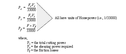
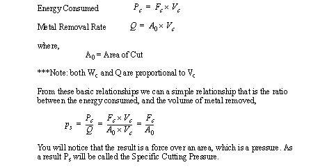
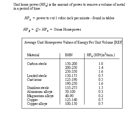
3.6 Power Consumed During Cutting
• There are a number of reasons for wanting to calculate the power consumed in cutting. These numbers can tell us how fast we can cut, or how large the motor on a machine must be.
• Having both the forces and velocities found with the Merchant for Circle, we are able to calculate the power,
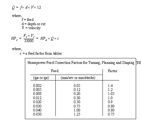
• We can relate the energy used in cutting to the mrr.
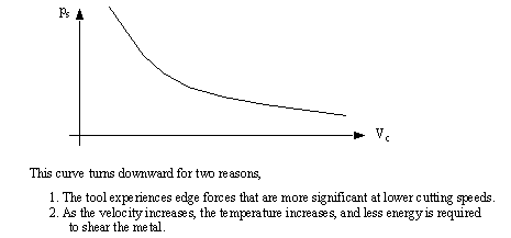
• The cutting force will vary, thus changing Ps, as the cutting velocities are changed.
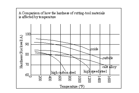
• Tool hardness is degraded by temperature, as shown in the diagram below [REF]
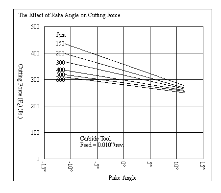
• The effects of rake angle on cutting are shown in the graph below, [REF ******]
• The horsepower required for cutting can be found using empirical methods,
• If we consider the implications these formulas have when cutting on a lathe, we would be able to develop the following equations,
3.7 Problems
Problem 3.1 An orthogonal cut is made with a carbide tool having a 15° positive rake angle. The various parameters were noted,
the cut width was 0.25”
the feed was set at 0.0125”
the chip thickness was measured to be 0.0375”
the cutting speed was 250 ft./min.
the forces measured were Fc = 375 lb. and Ft = 125 lb.
a) Use Merchant’s Circle to scale, and the velocity diagram
b) From the Merchant Circle diagram find the shear angle (φ), friction force (F), friction normal force (N), and shear force (Fs).
c) From the Velocity diagram find the friction velocity (Vf).
d) Calculate values for the coefficient of friction (mu) and the metal removal rate.
e) Calculate values, and compare the results for the results found in a), b) and c).
Answer 3.1 F = 218lb., N = 330lb., φ= 19.37°, Fs = 312 lb., μ= 0.948, Vc = 250 ft./min., Vf = 83.5 ft./min. Q = 9.375 in3/min.
Problem 3.2 The cutting forces for a lathe are listed below,
• work RPM = 125
• feed/rev = 0.005”
• chip thickness = 0.0123”
• rake angle of tool = 14°
• Ft = 150 lb, Fc = 245 lb
• work diameter = 8”
a) Find the horsepower consumed in cutting, shearing and friction.
b) Find a maximum lathe horsepower, assuming the machine efficiency is 95% and it requires 1/8 idle horsepower.
c) Based on the cutting horsepower, what material(s) might we be cutting?
Problem 3.3 What roles do rake and relief angles play in cutting tools?
Answer 3.3 The rake angle will change the basic cutting parameters. A positive rake (sharp tool) will give lower cutting forces, but less edge strength. A negative or neutral rake will give higher cutting forces, but more strength. The relief angle provide a gap behind the cutting edge so that the tool does not rub the work.
Problem 3.4 Which of these statement is the most correct?
a) a continuous chip with built up edge may result when we try to cut too much metal.
b) a continuous chip will result when cutting very brittle work materials.
c) a discontinuous chip will result when we use fine feeds and speeds.
d) none of the above.
Answer 3.4 A
Problem 3.5 One of the assumptions behind orthogonal cutting is,
a) that the rake angle is positive.
b) that the tool is only cutting with one edge and one point.
c) the shear plane is a function of before and after chip thicknesses.
d) none of the above.
Answer 3.5 B
Problem 3.6 Which of these statements is correct?
a) the cutting pressure drops as cutting velocity increases.
b) power required drops as metal temperature and cutting velocity increase.
c) we can use the quantity of metal removed by itself to estimate the required horsepower of a machine tool.
d) all of the above.
Answer 3.6 A
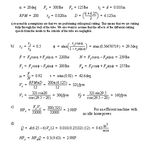
Problem 3.7 A lathe toolbit with a rake angle of 20° is cutting a section of pipe with an inner diameter of 6” and an outer diameter of 6.25”. The cut has a depth of 0.010” and the chip has a thickness of 0.020”. If the lathe is turning at 200 rpm, and the measured cutting forces are Fc = 300 lb, and Ft = 125lb,
a) what assumption must you make.
b) find the following values using a graphical or numerical solution: (Marks are only awarded for correct answers) Fs, FN, F, N, τ, φ, μ, Vc, Vf, Vs.
c) what is the minimum horsepower required for the machine?
d) given that the tube is aluminum, use another method to find the required horsepower.
Answer 3.7
Problem 3.8 Calculate the machine tool spindle speeds for the following:
a) Milling with a tungsten carbide tipped face cutter on a stainless steel work piece. C.S. = 65 m/min., cutter dia. = 150mm.
b) Drilling with a High Speed Steel drill in Machine Steel work, with C.S. = 70 ft./min., and a drill diameter of 19/32”
c) Turning on a lathe with a High Speed Steel tool in a mild steel work piece. Surface cutting speed = 100 ft./min., and a workpiece diameter of 2.75”
d) Milling with a High Speed Steel cutter in tool steel work with a cutter speed of 60 ft./min., and a cutter diameter of 3/4”.
Problem 3.9 Short answer,
a) Why are ceramics normally provided as inserts for tools, and not as entire tools?
b) List the important properties of cutting tool materials and explain why each is important.
Answer 3.9 a) Ceramics are brittle materials and cannot provide the structural strength required for a tool.
b) hardness at high temperatures: this provides longer life of the cutting tool and allows higher cutting speeds.
toughness: to provide the structural strength needed to resist impacts and cutting forces
wear resistance: to prolong usage before replacement
doesn’t chemically react: another wear factor
formable/manufacturable: can be manufactured in a useful geometry
Problem 3.10 A turning cut was made in a magnesium workpiece with a feed of 0.050ipr. The cutting speed was 300 fpm, and the cutting force was measured as 200lbs. The lathe is 95% efficient and has an idle horsepower of 0.1HP. Using all of the provided information estimate the horsepower required for the cut.
Answer 3.10
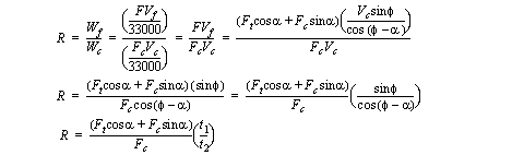
Problem 3.11 Develop an expression that is the ratio friction power over cutting power using the equations for orthogonal cutting power. Simplify the expression to be in terms of measured values (rake angle, Fc, Ft, and chip thicknesses).
Answer 3.11
Problem 3.12 A new lathe tool is to be used on cast iron work with a 6” diameter to make a 5” long rough cut in 3 passes. The operation conditions listed below were provided by the supplier or assumed. Calculate the parameters a) to e) as requested.
Cutting Speed = 300 fpm
Feed Rate = 0.008 ipr
Depth of Cut = 0.125”
Idle Horse Power = 0.25
Machine Efficiency = 0.90
a) Spindle RPM
b) Time to make the cut (min.)
c) Metal Removal Rate Q (in.3/min.)
d) Cutting Horse Power (HPc)
e) Minimum Machine Tool Motor HP.
Problem 3.13 Which of these statement is most correct?
a) a continuous chip with built up edge may result when we try to cut brittle metals.
b) a continuous chip will result when cutting very strong work materials.
c) a discontinuous chip will result when we use heavy feeds and speeds.
d) all of the above.
Answer 3.13 C
Problem 3.14 One of the assumptions behind calculating orthogonal cutting forces is,
a) that the rake angle is positive.
b) that the tool is only cutting with one edge and one point.
c) the shear plane is a function of before and after chip thicknesses.
d) none of the above.
Answer 3.14 C
Problem 3.15 Which of these statements is most correct?
a) the cutting pressure drops as cutting velocity decreases.
b) power required to cut each cubic inch drops as cutting velocity increases.
c) we can use the quantity of metal removed by itself to estimate the required horsepower of a machine tool.
d) all of the above.
Answer 3.15 B
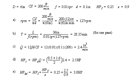
Problem 3.16 A new lathe tool is to be used on cast iron work with a 6” diameter to make a 36” long rough cut in 4 passes. The operation conditions listed below were provided by the supplier or assumed. Calculate the parameters a) to e) as requested.
Cutting Speed = 200 fpm
Feed Rate = 0.010 ipr
Depth of Cut = 0.100”
Idle Horse Power = 0.25
Machine Efficiency = 0.90
a) Spindle RPM
b) Time to make the cut (min.)
c) Metal Removal Rate Q (in.3/min.)
d) Cutting Horse Power (HPc)
e) Minimum Machine Tool Motor Horse Power.
Answer 3.16 a) 127rpm, b) 113min., c) 2.4 ipm, d) 1.23 or 3.94HP, e) 1.62 or 4.63HP
Problem 3.17 a) Define machinability. b) What determines the machinability of a metal?
Problem 3.18 What factors will affect surface finish?
Problem 3.19 Sketch a single edge cutting tool and label the a) face, b) flank, c) nose, d) cutting edge, e) relief, f) shank.
Problem 3.20 Why is the cutting speed important? What will happen at different cutting speeds, from very slow to very fast?
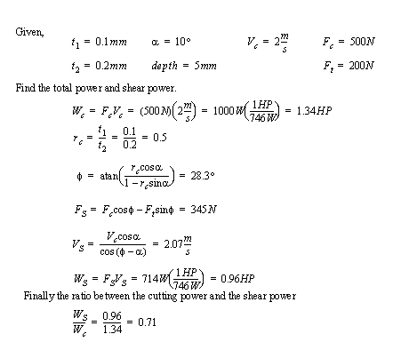
Problem 3.21 We have set up a lathe and are doing an orthogonal cut. The feed rate of the lathe is 0.1mm, and the chip thickness after the cut is 0.2mm. The depth of the chip being cut is 5mm. The surface cutting speed of the tool is 2m/s. The tool has a rake angle of 10deg. The tangential force is measured as 200N, and the cutting force is 500N. a) Calculate the shear force and velocity. b) Calculate the total energy produced in the cut, c) Calculate the energy used to shear d) Explain the difference between the total and the shear energy. [based on Kalpakjian]
Answer 3.21
Problem 3.22 How is machining different than other processes?
Problem 3.23 What is the difference between a roughing and finishing operation? How does this affect the workpiece and the power consumed?
Problem 3.24 What type of chip is expected at higher cutting speeds?
Problem 3.25 Does the friction power in cutting increase more with a feed or speed increase?
Problem 3.26 Why does cost typically increase for finishing operations.
Problem 3.27 Explain the correction factor ‘c’ used with the HPu values.
Answer 3.27 The HPu values are not linear, and ‘c’ corrects for these non-linear values