7. Process PlanningThis chapter is intended to give the reader a perspective for the research issues in CAPP. It will begin with a discussion of modeling process plans and designs. Then it will discuss a number of approaches to process planning. The chapter will finally conclude with brief descriptions of other CAPP systems. If the reader desires more extensive descriptions than presented here, then they are directed to other publications [Chang and Wysk, 1985][Wang and Wysk, 1988][Chang, 1990][Alting and Zhang, 1988][Requicha and Vandenbrande, 1988]. More advanced research directions in CAPP were discussed by Ham and Lu [1988, 1989], and ElMaraghy [1993]. Eversheim and Shulz [1985] have done an extensive survey on the use of CAPP systems by industry. Their paper identifies a number of the popular factors considered in CAPP systems. The majority of the systems they surveyed included, searching similar process plans (Variant), determination of raw materials, There were other less popular features found in some of the other systems, While these do not represent all possibilities considered within a CAPP system, they do indicate the features that are of importance to industry. Eversheim and Schulz also identify the major domains of CAPP systems. The most popular is rotational parts, followed by prismatic parts, sheet metal, assembly, etc. Their figures indicate a definite lack of multi-domain CAPP systems. Their paper also indicates that 70% of CAPP systems are used in facilities that focus on single part and batch production. A classification scheme for process planning was also suggested in Eversheim and Schulz [1985]. They divided CAPP functions into three major divisions, with sub-divisions; modification of process plan data.They present a table of the surveyed systems using the classifications given above. A larger table was presented by Alting and Zhang [1988]. Before discussing the details of how process planners operate, it is worth a short consideration of the planning context. There are a number of inputs to planning systems as reported in Lenau [1992]. These vary widely, and can have drastic effects on the abilities of the planner. At the output there are a number of factors required for complete process plans, but previously established manual methods have provided a thorough understanding of the requirements. 7.3.1 Process Plan ModelingIt is necessary to specify what information will be requested in a process plan that is modelled in a particular system. While the decision seems obvious there are a number of fundamental factors to be considered. First, there is the process description that varies greatly between each technology and manufacturing facility. Second, and more challenging, is the relationship (such as operation precedence) between operations. When dealing with a simple linear plan all we have is a list of operations. If the process plan is non-linear it can have parallel or alternative operations and we must look to more sophisticated representations. Assuming the non-linear process plan is stored in a graph, then the nodes and arcs could be assigned in a number of ways. Resources (typically machines or capacity groups) When dealing with assembly process plans this can be represented with numerous Bill Of Material (BOM) and operation sheets. The state of Work In Process (WIP) is well suited to inspection planning for parts. Routings and Work orders are better suited to batch orders where the production conditions may vary. All of these methods represent various manifestations of the fundamental data. The data itself has a few important data structure requirements, alternate plans for a workpart, a list of operations in a plan (with precedences), alternate operations for an operation in a plan, a list of steps for an operation (with precedences), alternate steps for each step, detailed data about each of the above levels of plan hierarchy. Many methods to date limit these requirements for practical reasons. For example XPS-2 [Nolan, 1989] uses a process plan structure which is shown in Figure 7.1 Process Plan Data Interface Specification (PPIS) Hierarchy. 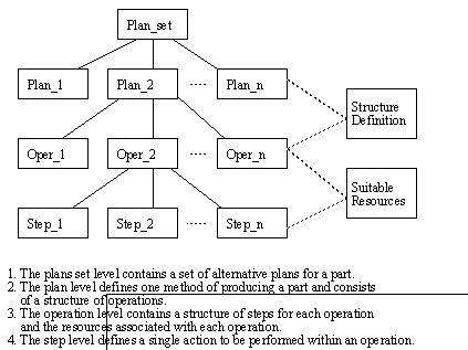
Figure 7.1 Process Plan Data Interface Specification (PPIS) Hierarchy This structure is further augmented with sequencing graphs to determine the precedence of the various plan steps. A method to indicate parallel, and alternative operations was reported by Tonshoff et. al. [1989]. They opted for a plan representation using Petri nets. Using this structure they were able to create plans that could be easily rescheduled when problems occurred on the factory floor that invalidated a process plan operation. A similar approach was adopted by Kruth and Detand [1992]. Mantyla [1993], suggested a process plan structure capable of defining process plans for the relationships between steps and alternatives for operations. 7.3.2 Product ModelingThe geometrical and non-geometrical knowledge about a product design can be difficult to represent formally. As a result many methods have been developed for representing a product design. B-Rep (Boundary Representation) CSG (Constructive Solid Geometry) Frames can be used to represent data that is in a fixed format, such as machining features. The example in Figure 7.2 Part of a Frame Based Feature Model was taken from Kusiak [1991]. In the example the feature is a rectangular pocket, and dimensions are given with tolerances. Other information such as surface finishes, and wall thicknesses are also given for planning purposes. Finally, the connectivity of the feature to other faces on the part is defined. 
Figure 7.2 Part of a Frame Based Feature Model Frames are fairly rigid in their form, and are therefore commonly used with feature based models. The reader should be aware that there are also examples where frames and features are not used together. These models experience difficulties when a nonstandard (not available in the modeler) feature is required [Karinthi and Nau, 1989][Shpitalni, 1991]. Many systems have been developed with feature based representations, such as Kjellberg et. al. [1990] and Hummel and Brooks [1986]. There are also CAD systems capable of doing design by features, such as those by H.A. ElMaraghy [1991] and Arikan and Totuk [1992]. More recent work has implemented features in an object oriented framework [Marefat et. al., 1993] [McNeilly, 1993]. For some extensive lists of features see Wilson [1983] and ESPRIT [1990]. Boundary Representation (B-Rep) has become the most popular method of representation for solid modelers and, as a result, for new CAPP systems also. B-Rep models explicitly define all of the faces on a solid, as well as the connectivity to other faces. But one problem with these models is that after the model is created, features must be recognized by examining sets of faces. It is difficult to associate feature type information with these models, because the feature is not present in the stored model. But, by far it is most difficult to extract a single feature when multiple features intersect. Constructive Solid Geometry (CSG) is a useful approach that carries high level information, and can be easily interpreted into B-Rep easily at any time, whereas conversion from B-Rep to CSG is very difficult [Brun, 1989]. Early work in CAPP has seen a simple CSG model used by Woo [1977], but there have not been many other uses since then. This method has a problem dealing with non-primitive shapes. At present there are some approaches to incorporating splined surfaces into CSG models, such as Ling et. al. [1987] who modelled sheet metal bends with CSG. Varady [1986] had investigated incorporating splined surfaces into the Build solid modeler (an early research solid modeler). He supplied a normal vector to identify outside surfaces, and he used the surfaces for CSG cuts. Some older methods rely upon input of data from 2D drawings. When used for rotational parts these can be very effective (turned parts can be considered 2D). But, when dealing with 3D objects, the model becomes ambiguous. Another older approach is based upon querying the user about the part in question. In effect the user answers questions from the computer and, as a result, a decision tree is traversed. Group Technology (GT) is a very popular abstract method for representing designs. It is used to identify subsets or families of similar parts for the purpose of realizing common features. This improves the design and process efficiency through standardization. The GT codes can be made to represent products by using any combination of geometry, manufacturing process, or function. The advantages of using such a coding system are standardization, reducing design proliferation, and it provides a basis for value engineering. To reduce the proliferation of new designs, GT can be used to perform searches for existing designs. The standardized plans also provide a basis for standard values for time and cost. In most cases GT codes are used in Variant systems, but in one case a Generative system was developed using a GT code as the basis for generating plan steps [Iwata et. al., 1987]. GT methods are highly sensitive to the specific GT code selected. Despite the attempt to create a standard code, the results always have to leave options for customization. Also, because GT codes are an abstract representation of a part, they do not carry enough detailed information for representing the part. There are a number of methods for planning. At the lower level we must consider decisions about databases, Artificial Intelligence, algorithms, etc. But, at the higher level we require decisions about the approach to planning, whether it is secretarial or creative. These decisions affect what the system will be capable of doing, and how it will be able to do it. This section starts off with a general discussion of the Variant and Generative approaches. A lengthy discussion of various methods for Generative planning follows this section. 7.4.1 Variant CAPP SystemsA Variant CAPP system is suited to dealing with a set of designs that tend to be variants of other standard designs. The basic concept is that new process plans are not completely redone when a new design is received. An existing process plan for a similar design is used as the basis for the new process plan. The old plan is edited to compensate for the differences. This reduction of human intervention provides advantages in terms of efficiency, reliability and standardization. But, human intervention is still required for adapting the plan for the new part. Nolan [1989] presents a thorough overview of Variant planning as well as making a good case for its use. There are also a number of papers discussing Variant planning systems [Emerson and Ham, 1982] [Carringer, 1984] [Mehta et. al., 1990]. Variant systems are probably best explained with reference to Group Technology (GT) codes. The decision to use GT should be determined by product variety. There must be a large number of parts that can be divided into groups, based on geometry, function, or production. The first implementation stage requires the development of a GT code. This code must then be verified. To verify the code, a sample of parts (10-20% of all parts is suggested) must be coded, then the results examined critically. If there is too much duplication, or too few similarities between codes, then the code should be corrected. After the code has been verified, the remainder of the parts should be coded. After all parts are coded, the GT system can be used for referencing stored designs and various associated information, like standard process plans. If standard process plans are also stored in the system, the GT code for a new part can be used to find a similar design and, consequently, a similar process plan. The GT code is made up of a string of digits or letters that identify specific features of a part. The entire string of digits may be related or unrelated. If they are unrelated, that is a polycode, then the meanings of the code are found using a list of features for each digit individually. If they are related, referred to as a monocode, they can be represented with a decision tree. In the decision tree, each digit would represent a branch in the tree. This allows the code to take on a wider variety of meanings. Hybrid codes are also used that are a combination of monocodes and polycodes. One example is the first GT system developed by the Dutch, called MICLASS [Nolan, 1989] which uses a four digit monocode followed by a polycode. An example of a GT code is seen in Figure 7.3 A Group Technology Example for the MICLASS GT Code. 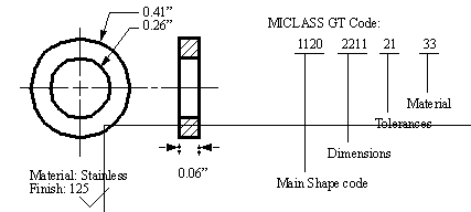
Figure 7.3 A Group Technology Example for the MICLASS GT Code There are some suggested guidelines for selecting the digits in a new GT code, they must differentiate products, must represent non-trivial features, only critical features should be encoded, every digit should be significant. Parts can be encoded using process flow, tool axis, tolerance, function, material, and shape. If a GT code is poorly chosen, there may be problems with too many or too few matches for the new GT codes, or the code might be inflexible to technological change. If the Group Technology code has been well implemented, it is easier to identify standardized routings, estimate work content, assure quality, and maintain the database integrity. There have been a number of approaches explored for applying GT to process planning. One of the common approaches is to follow the procedure for coding parts in a factory. After the parts are coded, standard part families and companion standard process plans are identified and stored using the GT codes. When a new design is developed a GT code is found for it. The GT code is then used to find the closest part family and, thus, a standard plan. Finally, the standard plan is edited to suit the new design. 7.4.2 Generative CAPP SystemsWhile the Variant method relies upon existing plans for the basis of process planning, Generative systems rely upon planning knowledge. Rules, algorithms, and heuristics about planning are used to recreate new process plans for each design. This allows process plans to be created with reduced human intervention, but at a large cost for the knowledge capture during implementation. The variety of approaches to this method have varied greatly. This introduction has been kept short because the remainder of this chapter will deal with the aspects of Generative systems, and the issues related to the implementation of such systems. A product model can be represented many ways. These range from basic geometric entities (such as lines) to abstract semantic networks of surface transitions. The representation affects how the model may be interpreted. Joshi and Chang [1990] give a list of methods. Constructive Solids Approaches Methods for process planning can be complicated, and techniques range from simple algorithms to Artificial Intelligence (AI). There is a great deal of work making a case for AI techniques, but there are also papers dealing with the advantages of algorithms [Halevi and Weill, 1992]. The work in all areas suggest that a judicious combination of both can yield a very successful CAPP system. 7.5.1 Expert SystemsThe most popular approach to recognition is using rules that are based upon human experience. The rules for an expert system are derived by a Knowledge Engineer who consults human experts. In general the rules are of the ‘if <conditions> then <action>’ form. As these rules are applied to a known set of facts, new facts are found. Most researchers use these rules to examine geometrical and manufacturing facts, in order to recognize manufacturing features. Some of the classic systems are excellent examples of rule based reasoning, such as GARI [Descotte and Latombe, 1984], TOM [Matsushima et. al., 1982], EXCAP [Davies and Darbyshire, 1984], XPLAN [Alting, et. al., 1988], etc. The expert system approach is well suited to designs stored symbolically. Other expert system approaches use Frame based reasoning or Decision Tables. It is quite common to augment data in a frame with connectivity (derived from B-Rep models) to other faces and features to facilitate symbolic condition testing. A good overview of expert system use in CAPP is available in Alting and Zhang [1988]. 7.5.2 Syntactic Pattern RecognitionBy encoding the geometry of a part using a set of grammatical symbols, an abstract expression may be formulated. A matching process may then be performed between the syntax of the derived grammatical expressions and grammatical syntaxes of known features. An example of this could be a representation of a sheet metal part. The part is described with line geometry, as pictured in Figure 7.4 Syntactic Pattern Representation of a Sheet Metal Design. A basic set of grammars are define for the shape. These are then applied to the shape to obtain a code for use in pattern matching. Here we see code for the part begins at the top left corner, and works around in a clockwise direction. 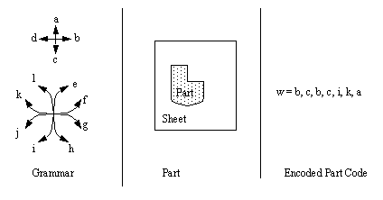
Figure 7.4 Syntactic Pattern Representation of a Sheet Metal Design Kusiak [1991] summarizes the process of Syntactic Pattern Recognition as three distinct stages. Initially, an input string (w = a1, a2, ..., an) and an extended context-free grammar (G = (Vn, Vt, P, S)), form the input to a schema. The context-free grammar is composed of, Vn set of input symbols described in the input string Vt set of symbols which will comprise the solution P a set of production rules which will transform the input string S (containing symbols Vn) into an output string G which contains The syntactic pattern recognition approach is used by Liu and Srinivasan [1984] to select machine tools for manufacturing parts. 7.5.3 State Transition DiagramsWhereas the Syntactic Pattern Recognition was based upon a large set of grammar, the State Transition approach uses a binary operator. When moving between previous features there are relative changes from concave to convex. These changes are marked with a state of 1 or 0 respectively. The profile of a part may be converted to a string, similar to the method shown in Figure 7.4 Syntactic Pattern Representation of a Sheet Metal Design. This is then fed to an automata which uses state transition diagrams to classify features. A State Transition Diagram may be seen in Figure 7.5 A State Transition Diagram for Feature Recognition. This example begins at the top left-hand corner, then proceeds in a clockwise direction. The only ‘1’ in the sequence represents the concave transition near the top right-hand corner. 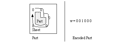
Figure 7.5 A State Transition Diagram for Feature Recognition The code for a part is then examined for recognized sequences (sub-strings). For example, if the shape encoded is for a power screw thread, the code would contain a string such as ‘......0011001100110011...’ (This is because of the square thread). Therefore, recognizing the string contains a power screw thread, the planner would be able to select the appropriate tooling, and cutting operation. 7.5.4 Graph-Based ApproachWhile Syntactic Pattern Recognition and State Transition Diagrams are best suited to planar parts and rotated profiles, graph-based approaches are suited to full three dimensional parts. Kusiak [1991] describes the form of the graph as G = (N, A, T) where, N represents nodes in the graph A represents arcs between nodes T represents attributes assigned to the arcs This basic method involves capturing the design geometry in the form of a graph. The graph is then examined for patterns that match known features. Joshi and Chang [1988] and Joshi, Vissa and Chang [1988] developed the Attribute Adjacency Graph (AAG). Each face is represented as a node. The arcs are the edges, or adjacency. The attribute of the arc is assigned a value of 0 or 1 depending upon a concave or convex transition, respectively. They then recognize features with algorithms and rules. The algorithms find candidates for indented features by examining the concavity of points. When potential features have been identified, the AAG is examined with production rules to compare features to feature graphs. They also deal with interacting features and there are three cases they discuss. The first is nested features, such as a pocket milled inside a pocket. In this mode, features are identified and then cut out of the AAG. The next case is intersecting features, such as two slots cut to cross each other. To detect this condition, virtual surfaces are created, then the features reexamined. Finally, when the forms of features interact, such as two stepped slots, the feature is dealt with by using virtual pockets. The important feature of these methods is the creation (or destruction) of new subvolumes to clarify feature details, and therefore simplify recognition. Their work was implemented for machined parts with indented features. Sakurai and Gossard [1988] have an interactive system which the user uses to identify significant faces in a feature by selecting faces on a B-Rep model. They can search a B-Rep model to identify subsets that correspond to known features. deFloriani[1987] categorizes recognized features into depressions, protrusions, and holes from a B-Rep Model. The simple features are then grouped into compound features. The final model is a generalized edge face graph. In general the syntactic pattern recognition, state transition diagrams, and graph based approaches are all suited to models that have some form of 2D or 3D B-Rep model. These methods can recognize features in an object, unless they overlap, but they are not able to reason past that stage. 7.5.5 Constructive Solids ApproachA very limited number of methods have examined the use of Constructive Solids Geometry (CSG), also known as the Set Theoretic method. The CSG method uses primitive volumes, and then performs additions, joins, and removes between them to form more complex objects. Eventually complex geometries can be built up. In some early work in the area of solid modelling, Woo [1977] developed a CSG based process planning method. His system allows design, process planning and then milling of cavities into parts. At the front end of the system is a solid modeler called CARVD. The system has two operations, ADD and REMOVE (a sub-set of the full CSG operations). The system puts the design into a nested algebraic expression, which is searched for cavity patterns. This search progresses from the most nested term to the least. The search involves determining ‘hooks’ between the terms in the algebraic expression. The system then uses interpretive rules (in the form of semantic nets) to match these to features (see Figure 7.6 The CARVD Method of Feature Recognition (Adapted from [Woo, 1977])). 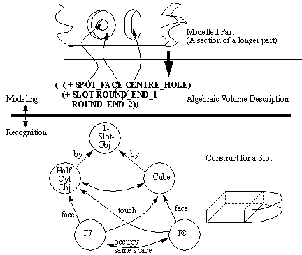
Figure 7.6 The CARVD Method of Feature Recognition (Adapted from [Woo, 1977]) After a feature is chosen, the NC code is generated. The procedure of selecting an NC tool path involves an approach direction for the feature. The method of NC code generation is highly specific to cavity milling. This method of casting the expression in a nested equation form is similar to the representation used in this thesis. Woodwark [1988] philosophizes about CSG approaches to Feature Recognition. He identifies the non-uniqueness of the CSG model as one of the faults of the method. He argued that the non-uniqueness of the method makes search spaces much larger, and therefore harder to search and prune. As a result, he suggested three ways to overcome these problems. Restrict the domain of the model, by restricting the range of primitives and orientations that they may assume (used in the work by Woo [1977]). To restrict the ways in which primitives may interact spatially. To restrict the allowable forms of set theoretic expressions which define the model. By limiting the complexity of the model, it is possible to limit the complexity of the designs is also limited. Woodwark also suggests matching to shape templates. This method involves using feature templates that are applied to local parts of the CSG model. This is similar to traditional pattern matching, except that it is localized for specific features to save search time. He claims this method can fail when two or more features interact, thus causing the feature matching to be inconclusive. The final approach proposed by Woodwark is a hybrid CSG and Boundary Representation. He discusses adding geometrical boundary information to the set theoretic model. In this way the benefits of CSG are maintained, while making the actual geometry available for geometrical reasoning. Work has been done by a number of authors to recognize features using CSG pattern recognition. Kakazu and Okino [1984] developed a method for converting a set theoretic representation of a part into a canonical form, and then a pattern recognition approach was used to find a Group Technology code. Other work for manipulating CSG trees was done by Goldfeather et. al. [1986] who developed the CSG tree into a normal form for faster computer graphics. Lee and Jea [1988] also developed a method for moving single nodes up through a CSG tree for the purpose of eventually developing a system that recognizes CSG features recognizing features. They only provided a brief description of how a feature recognition algorithm would work. 7.5.6 DecompositionThe method of the previous section is successful, but assumes that the CSG operations are all subtractions of machined features. But, this is not always the case, sometimes a larger stock shape must be selected before features can be recognized. After the stock is selected, solid models can be decomposed into smaller subvolumes through iterative methods. These subvolumes may then be examined by a feature recognition stage. There are common methods often used for this technique. These methods are often based on some sort of differencing operation to derive sub-volumes. Ruf and Jablonski [1990] discuss their integrated CAPP and PPC system. One of the modules for feature recognition is called Feature Recognition Extraction, Decomposition and Organization System (FREDOS). This module will take a design represented in B-Rep, and select a piece of stock to machine from. The boolean difference between the stock and the part is calculated. This remainder is then decomposed into individual features. The features then specify a generic process plan, without machines specified. A method of overcoming the non-unique properties of CSG representations has been suggested by Tang and Woo [1991a,b]. Their papers discuss a method of decomposing a solid into a set of convex solids. This is done using an iterative method of covering an existing part with a convex hull. The hull then has the basis part subtracted. The same operation is continued on the remaining solid until there is no solid left. The result is a set of volumes that may be resolved into a set of removable volumes. An example from their paper is shown in Figure 7.7 The Alternating Sum of Volumes (ASV) (the figures depicted here are not to scale for clarity) [Tang and Woo, 1991a,b]. In the example, the part goes through a number of iterations to identify the primitive geometry components. At the bottom of the figure the primitives are collected and then simplified to material removal only. The very bottom of the figure shows a set of primitive shapes that may be removed (H1’ and H3) from the stock (H0) to produce the part. 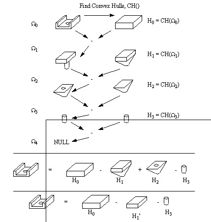
Figure 7.7 The Alternating Sum of Volumes (ASV) (the figures depicted here are not to scale for clarity) [Tang and Woo, 1991a,b] Although this method will determine a set of machinable features, it has some problems which the authors also identified. Tang and Woo [1991b] refer to these problems as nonconvergence. And, considering that this method is iterative, the algorithm would continue indefinitely, as shown in Figure 7.8 An Example of a Nonconvergent ASV. The have proposed an algorithm to check for nonconvergence based upon strong, weak, and internal hull vertices. They present a set of algorithms, in pseudocode, that deal with a Boundary Representation. These algorithms have also been developed to deal with non-manifold edges and vertices. 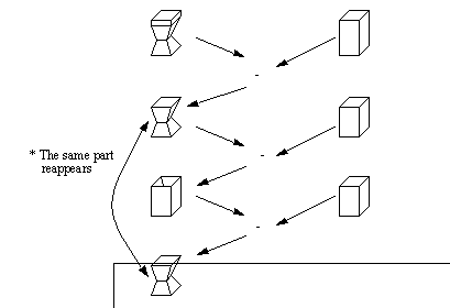
Figure 7.8 An Example of a Nonconvergent ASV In general, a decision must be made about the method of producing a part. Almost all previous CAPP research has limited itself to fixed domains, such as machining, turning, injection mold making, etc. This has simplified the planning process, but it does not allow for parts that are produced using a number of different manufacturing technologies. For the purpose of illustration this section will discuss a system for machining techniques. At the end of this section the reader should have an appreciation for what parameters are normally covered when doing operation planning. 7.6.1 Selection of Machining ProcessesMachining is distinguished by the successive removal of material. The order of removal, the tools and fixtures chosen, and other factors all have a profound impact on the cost. As discussed before, a good mix of AI and algorithms will result in a more successful system, and this will be obvious throughout this section. A machinable volume is the amount of material that may be removed in one tool pass. If we consider a volume of material to be removed, it may then be divided into a number of machinable volumes. Processes are selected for removing the machinable volumes. Criteria which may be considered when selecting machinable volumes are; shape, size, dimensional and geometric tolerances, surface finish, etc. Many processes are also multi-step, and may require preparatory processes. Process selection is often done with Rules, Frames, and other methods (see the examples in Figure 7.9 Rules or Frames for Process Selection (Adapted from [Kusiak, 1991])). 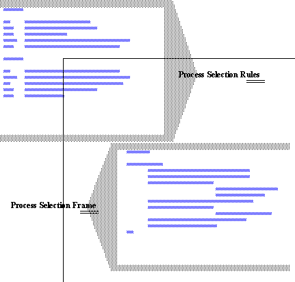
Figure 7.9 Rules or Frames for Process Selection (Adapted from [Kusiak, 1991]) Similar rules are also used in XPS-2 [Nolan, 1989], GARI [Descotte and Latmobe, 1984], etc. 7.6.2 Selection of Machine ToolsThere are many ways to choose machining details such as: tools, coolants, fixtures, etc. Methods for selecting include rules, frames, etc. (see Figure 7.10 Rules and Frames for Machine Selection (Adapted from [Kusiak, 1991])). 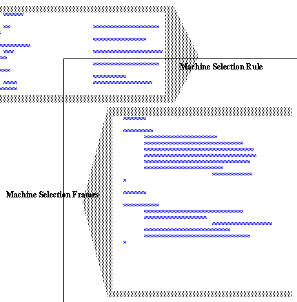
Figure 7.10 Rules and Frames for Machine Selection (Adapted from [Kusiak, 1991]) 7.6.3 Machining OptimizationThe very nature of manufacturing is such that a manufacturer must survive through outperforming the competition. To do this there are a number of objectives the manufacturer will try to meet through optimizing some aspects of production. These objectives vary, and alter how decisions are made within the factory. Process planning has a large effect on the cost of production. By considering optimization of processes during the planning there can be considerable savings. The machining optimization problem has some fundamental elements found in all optimization problems. Cost tends to rule all decisions. This results from a number of interrelated factors, Each of these can be estimated using approximations. For example, tool wear may be estimated using Taylor’s tool life equation, 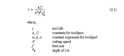
Machining time is greatly affected by the number of passes. The single pass model is fairly simple, and can be formulated as a constrained optimization problem. The multi-pass model is similar, but has added parameters to account for the multiple passes. Kusiak [1991] discusses the model shown in Figure 7.11 Parameters of the Multi-pass Machining Model (Adapted from Kusiak [1991, pp. 261-262]). Please note that the single-pass model is ignored because it may be easily derived from the multi-pass model. 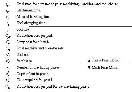
Figure 7.11 Parameters of the Multi-pass Machining Model (Adapted from Kusiak [1991, pp. 261-262]) 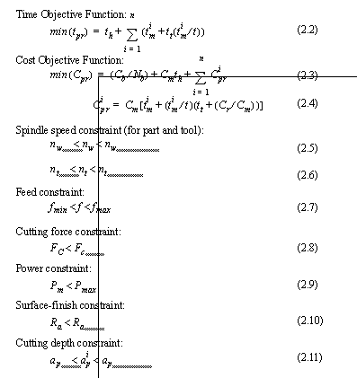
Figure 7.12 Objective and Constraints of Multi-pass Machining Model There are many approaches used for optimization. Challa and Berra[1976] used a gradient search method. Chang et. al. [1982] used dynamic programming, after putting some variables in the discrete domain. Kusiak [1987] presents a hybrid system for knowledge based, and numerical optimization of the problem. 7.6.4 Optimal Selection of Machinable VolumesA large machinable volume will require multiple passes of a tool. To determine the sub-volumes, it should be decomposed using some geometrical methods. The example in Figure 7.13 Decomposition of a Machinable Volume shows how a part has been decomposed by extending the planes describing the surfaces. 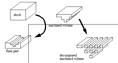
Figure 7.13 Decomposition of a Machinable Volume This decomposition is easily accomplished if the planes existing in the part, are extended, and used as cutting planes, for the machined volume. When a machinable volume has been decomposed, each of the volumes may be further sub-divided into elemental volumes. The fully decomposed volume is shown in Figure 7.14 A Machinable Volume Sub-Divided into Elementary Volumes (Adapted from [Kusiak, 1991]). 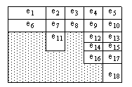
Figure 7.14 A Machinable Volume Sub-Divided into Elementary Volumes (Adapted from [Kusiak, 1991]) After dividing the machinable volume, the problem may be approached as an optimization problem. The list of variables in Figure 7.15 Decision Variables for Optimal Machinable Volume Selection (Adapted from [Kusiak, 1991]) defines the decision variables involved with the problem. The Objective function, and the constraints are shown in Figure 7.16 Objective and Constraints for Selection of Machinable Volumes (Adapted from [Kusiak, 1991]). This formulation is taken from Kusiak [1991]. He states that this formulation should be complete. He also states that some of the constraints and variables may be ignored in some problems. 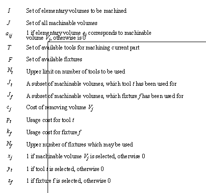
Figure 7.15 Decision Variables for Optimal Machinable Volume Selection (Adapted from [Kusiak, 1991]) 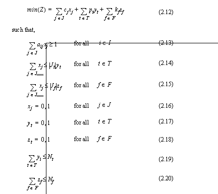
Figure 7.16 Objective and Constraints for Selection of Machinable Volumes (Adapted from [Kusiak, 1991]) The example in Kusiak [1991] goes on to show a machinable volume matrix, shown here in Figure 7.17 A Machinable Volume Matrix (Adapted from [Kusiak, 1991]). The matrix shows that there are a number of possible ways to machine the volumes (not all must be used). These volumes also correspond to costs, tools, and fixtures (shown in Figure 7.18 Example Sets for Machinable Volume Matrix). These also generate a precedence graph (shown in Figure 7.20 Precedence Graph and Rules for Machinable Volumes (to Produce the Precedence Relations)). 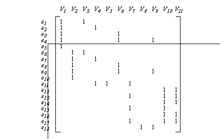
Figure 7.17 A Machinable Volume Matrix (Adapted from [Kusiak, 1991]) 
Figure 7.18 Example Sets for Machinable Volume Matrix In addition to this, the constraints that Nt = 3, and Nf = 2 are added for this example. The resulting solution is developed using unspecified optimization techniques, and is shown below in Figure 7.19 Solution for Example Problem. 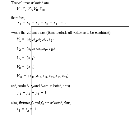
Figure 7.19 Solution for Example Problem The solution produces an objective function value of Z = 23. Kusiak claims that this solution reduces cutting costs by as much as 8%, and reduces the tool and fixture count over traditional methods. To continue this example, consider that the sequence of operations is not yet determined. This may be done using simple rules about volume relations. The relations are mainly based on i) accessibility of volume, and ii) datums for tolerances. Some examples of rules are given by Kusiak [1991], and shown here in Figure 7.20 Precedence Graph and Rules for Machinable Volumes (to Produce the Precedence Relations). 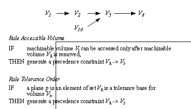
Figure 7.20 Precedence Graph and Rules for Machinable Volumes (to Produce the Precedence Relations) After the precedence constraints have been determined, the operations must be sequenced. This is done by first checking to see that there are some start nodes, with no predecessors, to ensure that the precedence graph is solvable. If it is then starting from the left the graph is expanded. The two possible sequences are {V1, V2, V10, V5, V8}, and {V1, V10, V2, V5, V8}. In his paper, Kusiak [1991] does not suggest how to resolve this dilemma, but does mention setup costs are one possible method. The work of Kusiak is of importance to this thesis when considering what BCAPP must do. By itself Kusiak’s work describes a complete operation planner for some forms of machining. But, without first selecting machining, and then specifying features to machined, it has reduced value. Therefore, after the process plan is completed by BCAPP, a system like the one described here should be used to select tools, cuts, speeds, feeds, etc. As CAPP becomes more accepted in the factory environment, it will become necessary to integrate it with other functions. According to Ham[1988, 89] the advantages of such a development would be, improved efficiency in the information flow, improved quality of the process planning, reduction of the human errors, functional integration of process planning and scheduling, enabling a quick search for alternative solutions for optimization in the use of equipment and production control, and, flexible use of the different functions. Ham [1988, 89] also asserts that there are certain key elements to a successful implementation of such a planner, a uniform product description based on proper features, the use of different modules for different functions, the use of a uniform user interface for each module, the use of a uniform data base for each module, the possibility of facilitating user interaction at the request of the operator. Finally Ham [1988, 89] describes the issues involved in integrating CAPP with the related manufacturing functions. Planning Knowledge: A mixture of physical properties, and knowledge heuristics. Planning Activities: Must be integrated with Production Planning, and with Operation Planning, including physical process models. Planning Techniques: A collection of many process planning techniques (like Group Technology, Rules, etc.) must be used to avoid problems with each, and find the best plan possible. Planning Constraints: Technological, and other constraints, should be considered during planning, not simply used after planning to eliminate plans. Planning Feedback: Information which results from previous process plans must be used to issue new plans, and avoid similar mistakes in the future. Some work has been done by various authors to address integrating CAPP with PPC. For example, Ruf and Jablonski [1990] discuss their system called FIPS. The system contains three modules, FREDOS (Feature Recognition, Extraction, Decomposition, and Organization System), SSM (Static System Manager), and DRS (Dynamic Resource Scheduler). Essentially FREDOS will identify the machinable features in the part. The SSM will then assign all possible combinations of machines to the process plan. The DRS module will dynamically schedule the jobs into various machines, depending upon the current status of all machines. Although this system is for a limited domain, it displays the important concept of delaying resource assignment until required. The CAM-I group began developing an interface specification for connecting CAPP to their factory management programs [a section by Sack, in Nolan, 1989]. The project began in 1986, at the UTRC at MIT, where they defined and reconciled terms, and developed a conceptual view of the standard database structure. They produced a Process Plan data Interface Specification (PPIS), which indicated interface subroutines used by the various computer programs. The diagram in Figure 7.21 PPIS Interface Between CAPP and PPC shows how their system is used to integrate XPS-2 and a factory control system called MADEMA. Other work has also been done by other groups on the general nature of integrated scheduling and CAPP. ElMaraghy [1992] examines bridging the data and functional gaps. Feedback of information about the resources was discussed by ElMaraghy, as well as Krause et. al. [1991] and Chryssolouris et. al. [1984]. 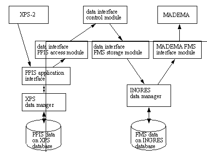
Figure 7.21 PPIS Interface Between CAPP and PPC Most CAPP systems have been through many revisions which can be illustrated through the simple grouping shown in Figure 7.22 Genealogy of Some Families of CAPP Systems. The order and relationships of these systems were found or deduced through the review of the literature discussed throughout this chapter. 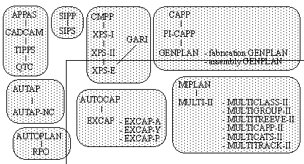
Figure 7.22 Genealogy of Some Families of CAPP Systems The list below summarizes some systems for Process Planning. Longer descriptions are given for some of the more well known systems. Systems without names are referred to by the authors name. The summary of each system should provide an overview to many of the planning approaches taken to date. APPAS, CADCAM [Chang et. al., 1982], TIPS [Chang and Wysk, 1985], QTC [Kanumurz et. al., 1988] [Anderson and Chang, 1989] [Chang, 1991]: APPAS (Automated Process Planning and Selection) models machined surfaces with special codes. Decision trees are used to direct the planner. It can handle multiple passes and operations for each surface. APPAS was extended into the CADCAM system to allow the use of an interactive graphic interface for design entry for direct use in process planning. This example was taken even farther in TIPPS that added a full graphical design system to allow the user to guide the CAPP system through a point-and-click interface. And, subsequent development lead to QTC (Quick Turnaround Cell). This system is based on a CSG type recognition system that plans from design to production. AUTAP, AUTAP-NC [Eversheim et. al., 1980]: AUTAP will first find a stock shape, then develop a set of operations to produce rotational parts. Operations are sequenced, time estimates are made and tools are selected. AUTAP-NC is a subsequent system capable of producing NC part programs to produce the turned components. CADCAPP [Kamvar and Melkanoff, 1986]: Describes a system that accepts a drawing of a turned part from a commercial CAD system, then uses an algorithm to assign a GT code. CAPES [Fujita and Oochi, 1989]: A generative system for prismatic parts. Uses a solid modeler. CIMS [Iwata and Sugimura, 1985]: Uses interactive solids modeling with associated technological information. A process plan is generated using the finished part, and a blank. The plan is generated using production rules in a knowledge base. The planning is done in a five step process: machined surfaces are identified, appropriate tools are selected, machined surfaces are grouped, precedence constraints are generated, and finally, a process plan is generated. Sequencing is done using matrix methods. CMPP [Dunn, in Nolan [1989]] [Parks et. al., 1989], XPS-I [Pavey et. al, 1986] [Groppetti, 1986] [Austin, 1986], XPS-II: For rotational, and other domains such as grinding, based upon representation. The planner analyses the machinability, then produces plans. This system contains the language COPPL described earlier in the chapter for manufacturing knowledge. A variety of research has been done on applying this system, such as accepting IGES files as input to eventually generate NC code [Knutilla and Park, 1990]. CUTTECH [Barkocy and Zdeblick, 1984]: Uses information from the user about features, machines, materials, etc. Generates a GT code for each feature, selects machine tools, cutting tools, etc. using rules from a knowledge base. A second knowledge base is used for selecting operation parameters like speeds and feeds. [Delbressine, 1989]: A system to develop a part using stock that is transformed using manufacturing objects based on swept tool geometries. EXCAP [Davies and Darbyshire, 1984] [Joseph and Davies, 1990] [Davies et. al., 1985] [Darbyshire and Davies, 1984]: Uses a limited description for rotational parts. Planning is divided into two steps, sequence planning, then operation planning. Rules are backward chained to prove hypothesis. If accepted the geometry is modified, and planning continues. This stage constructs a tree where the root is the finished part, and the leaves are blanks. The final tree has branches with certainties associated with each. Plans can be easily generated from the tree, and if rejected, alternate plans are easily generated. A further exploration with an application was done by Joseph [1989]. EXPLAIN [Prabhu et. al., 1990]: A feature based system that generates process plans for turning using rules. EXPLAN [Warnecke et. al., 1989]: Describes a generative planner using a graphical interface. FEXCAPP [Lee et. al., 1989]: Uses connectivity graphs and then does pattern matching to find features. FLEXPLAN [Lampkemeyer et. al, 1991] [Tonshoff et. al., 1989]: Uses Petri nets to represent non-linear process plans. FLEXPLAN can store, generate, and schedule for non-linear process plans. FRAPP [Henderson and Chang, 1988]: A system that does B-Rep based feature recognition, then some process planning based on the features. GAPP [Laperriere and ElMaraghy, 1992]: An assembly planner using part connectivity and an A* search. GARI [Descotte and Latombe, 1984]: Parts are described with feature descriptions, dimensional locations and tolerances of features, and other information like materials and finishes. An initial loosely constrained plan is developed, then a hierarchical planning system is applied in an iterative manner to suggest operations, propagate constraints, and backtrack. GCAPPS [Pande and Palsule, 1988]: A system for feature based design of rotational parts. Genoa [Held and Juttner, 1991]: Uses rules to generate plans in a limited domain. [Han et. al., 1987]: A semi-generative system. [Henderson, 1986]: A method for recognizing holes, slots and pockets. Faces are identified, then their relationships are determined, and converted to solid features with a connectivity graph. Hi-Mapp [Berenji et. al., 1986]: Parts are represented with feature descriptions, locations, tolerances, and other manufacturing information. An abstract, but correct plan is generated. A hierarchical planning system is applied, which operates using priorities. The knowledge base contains rules for selecting processes, recommending cuts and machines, and recommending other user defined options. KAPPS [Iwata, 1988]: An expert process planner for machining using over 600 rules. KCAPPS [Wei et. al., 1990]: An AI generative system with an interactive interface for defining manufacturing attributes. Uses CSG subtractions of features from various sources of stock. [Lee and Wang, 1990]: Does robotic assembly planning. They use features and rules to get a) largest feature stability, and b) heaviest part, and then rank the assembly order. It then generates robot path parameters for a complete off-line programming system. MicroCAPP/GEPPCAPP [Wang and Wysk, 1985 a b] [Wang, 1984] [Cachia and Vajpayee, 1986]: Complementary systems that have MicroCAPP, a code based variant planning system, and GEPPCAPP, a decision tree based generative planner. MiniCIM [Shyu et. al., 1987]: A complete design to manufacture system for turning. PART [vanHouten et. al., 1984] [Jonkers and Kals, 1992], PART-S [deVin et. al., 1992]: A generative system that does both process and production planning. Another implementation is PART-S for doing sheet metal planning. PC-CAPP [Pande and Walvekar, 1989]: A feature based CAPP system for prismatic parts for a specific corporation. Primarily a rule based data-base lookup package. [Phillips et. al., 1985]: Discusses a profile based planner. [Preiss and Kaplansky, 1984]: A system that goes directly from design to NC milling. PROPLAN [Phillips, 1984] [Phillips and Mouleeswaran, 1985]: Primitive lines and arcs, describes a symmetrical rotational part. Production rules are stored in a database and applied using a graph search. The graph nodes are the parts geometry, the arcs are the transformation operations. PWA_Planner [Chang and Terwilliger, 1987]: Does assembly planning for circuit boards. ROUND [vanHouten and Kals, 1984]: A generative system for turned parts. SAPT [Milacic, 1985] [Milacic and Vrosevic, 1984] [Milacic et. al., 1988]: Three modules are used, the first is technological pattern recognition, which defines detailed structure of process planning. Secondly, the manufacturing process logic module defines logical relationships between the part, machine, fixture, and operation sequence. The rules for these tasks are stored in a knowledge-base, along with rules for the strategy of planning. [Schneider et. al., 1989]: Their system attempts to match rules for rotational parts by examining the 2D profiles. SIPP [Nau and Chang, 1985]: Hierarchical frames are used to represent parts, where a frame will represent a feature, and other frames define the properties of the feature. A search strategy using least cost first, is used in conjunction with a knowledge base relating features, to machining processes. The nodes of the graph represent parts, and the arcs are the operations that transforms them. Process restrictions are considered in generation of the graph. TOM [Matsushima et. al, 1982] [Iwata and Sugimura, 1984]: Technostructure Of Machining uses a final design, a collection of holes, and backward chains a set of production rules to develop an optimal process plan. When conflicting rules are found heuristics are used, including frequency of application. TOPS [Pinte, 1987]: A system that uses frames, constraints and rules with a truth maintenance system for planning. [Willis et. al., 1989]: A system that uses a solid modeler based on an expert system. Non-linear planning is supported. XCUT [Hummel, 1989] [Hummel and Brooks, 1988]: Uses a hierarchical layering of rules Even more important is the use of Meta-knowledge to select between modules of rules. XMAPP [Inui, 1986]: Does forward planning using a product model like GARI. XPLAN [Alting, Zhang and Lenau, 1988], XPLAN-R [Zhang and Alting, 1988 a, b]: A planning system for rotational parts based on DCLASS. The successor is XPLAN-R. XPS-1 [Groppetti and Semeraro, 1986], XPS-2 [Nolan, 1989], XPS-E [Chryssolouris et. al., 1986]: A interesting line of generative CAPP systems have been developed from the CMPP project, eventually evolving into the XPS-E system. CMPP (Computer-Managed Process Planning) was originally developed at United Technologies [Mark Dunn in Nolan, 1989]. It is a process planning system which is Generative, and Automatic, and capable of handling rotational parts. After the data entry module is done the Process Planning module will begin. Its four functions are; generate a summary of operations, select tolerancing datums, determine dimensions and tolerances, output process documentation. The Computer Aided Manufacturing-International (CAM-I) group has been developing a process planning system. This has been done through a set of projects dubbed XPS-N [Sack authored a section in Nolan, 1989]. The first system in this line was XPS-1, which was completed in 1984. The system provides an environment for process planning, using feature based product data, and manufacturing resource data. This information is stored in a relational database. Rules are used to provide the logic for process planning. The second prototype system, XPS-2 was completed in 1987. Other CAM-I design projects were used as an interactive front end for collecting feature information including, geometry, dimensioning, and tolerancing. An attempt to use Artificial Intelligence was proposed with XPS-E. This was done using a report commissioned from two French organizations, Institut National Polytechnique de Grenoble (INPG) and Industrie et Technologie de la Machine Intelligente (ITMI). Their method conformed to the ideal of the XPS-N Philosophy, but augmented it with Artificial Intelligence techniques. This chapter has discussed the fundamentals of CAPP research, including product modelling, process plan modelling, Variant and Generative systems. It then went on to discuss techniques used for interpreting the product model. A detailed look at a CAPP system for machining is then presented, including operation planning. Finally, a list of many of the systems reviewed is given, with a brief description of each. At this point the reader will have some appreciation for the implementation of CAPP systems, and the environments they operate in. Most of the techniques discussed in this section can be used when planning for specific technologies, but there is a notable absence of techniques for planning across multiple manufacturing domains. In terms specific to the thesis, process planners described in this section are all best suited to the Operation Planning aspects of CAPP, as will be covered in Chapter 6. |