2. Circuit Analysis
• The techniques of circuit analysis focus on trying to derive equations that describe a circuit.
• In general most of the techniques attempt to simplify analysis by breaking the circuit into parts, loops, etc.
• Some well known techniques include,
mesh currents
node voltages
superposition
Thevinen and Norton equivalents
2.1 Kirchhoff's Laws
• Kirchhoff’s Current Law: “The sum of currents at any node in a circuit must equal zero”: keep in mind that current is a flow rate for moving electrons. And, electrons do not appear and disappear from the circuit. Therefore, all of the electrons flowing into a point in the circuit must be flowing back out.
• Kirchhoff’s Voltage Law: “The sum of all voltages about a closed loop in a circuit is equal to zero”: Each element will have a voltage (potential) between nodes. If any two points on the closed loop are chosen, and different paths chosen between them, the potentials must be equal or current will flow in a loop indefinitely (Note: this would be perpetual motion).
2.1.1 Simple Applications of Kirchhoff’s Laws
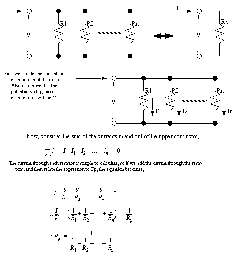
2.1.1.1 - Parallel Resistors
• Let’s consider one on the most common electrical calculations: that for resistors in parallel. We want to find the equivalent resistance for the network of resistors shown.
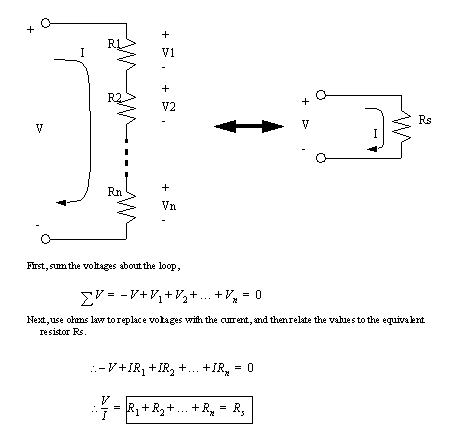
2.1.1.2 - Series Resistors
• Now consider another problem with series resistors. We can use Kirchoff’s voltage law to sum the voltages in the circuit loop. In this case the input voltage is a voltage rise, and the resistors are voltage drops (the signs will be opposite).
2.1.2 Node Voltage Methods
• If we consider that each conductor in a circuit has a voltage level, and that the components act as bridges between these, then we can try some calculations.
• This method basically involves setting variables, and then doing a lot of algebra.
• This is a very direct implementation of Kirchoff’s current law.
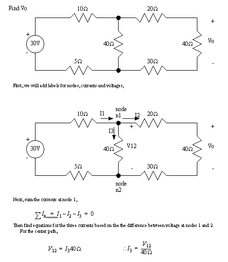
• First, let’s consider an application of The Node Voltage method for the circuit given below,
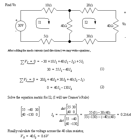
2.1.3 Current Mesh Methods
• If we consider Kirchoff’s Voltage law, we could look at any circuit as a collection of current loops. In some cases these current loops pass through the same components.
• We can define a loop (mesh) current for each clear loop in a circuit diagram. Each of these can be given a variable name, and equations can be written for each loop current.
• These methods are quite well suited to matrix solutions
• Lets consider a simple problem,
2.1.4 More Advanced Applications
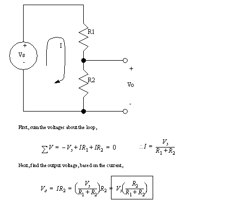
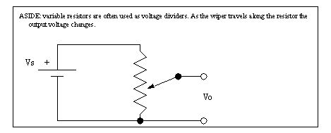
2.1.4.1 - Voltage Dividers
• The voltage divider is a very common and useful circuit configuration. Consider the circuit below, we add a current loop, and assume there is no current out at Vo,
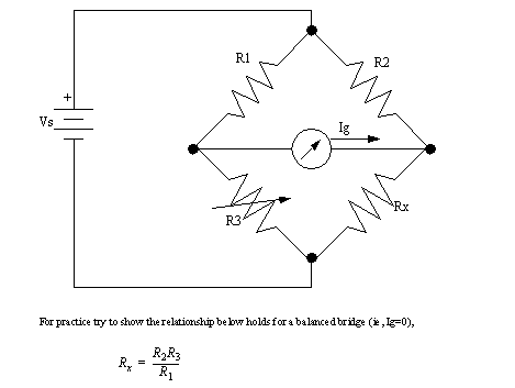
2.1.4.2 - The Wheatstone Bridge
• The wheatstone bridge is a very common engineering tool for magnifying and measuring signals. In this circuit a supply voltage Vs is used to power the circuit. Resistors R1 and R2 are generally equal, Rx is a resistance to be measured, and R3 is a tuning resistor. An ammeter is shown in the center, and resistor R3 is varied until the current in the center Ig is zero.
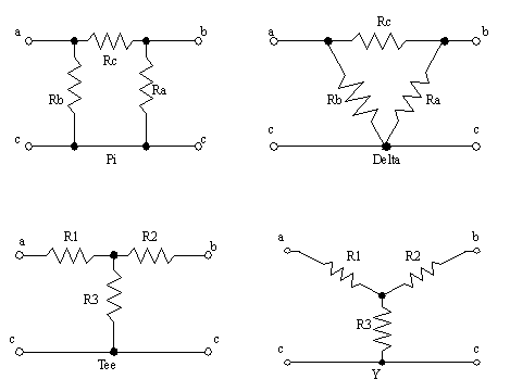
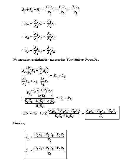
2.1.4.3 - Tee-To-Pi (Y to Delta) Conversion
• It is fairly common to use a model of a circuit. This model can then be transformed or modified as required.
• A very common model and conversion is the Tee to Pi conversion in electronics. A similar conversion is done for power circuits called delta to y.
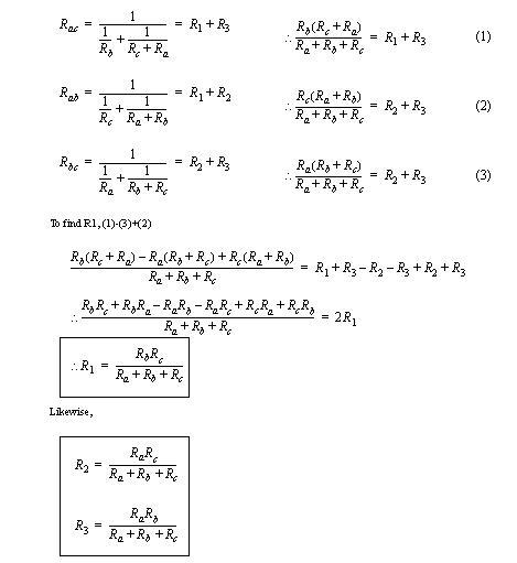
• We can find equivalent resistors considering that,
• To find the equivalents the other way,
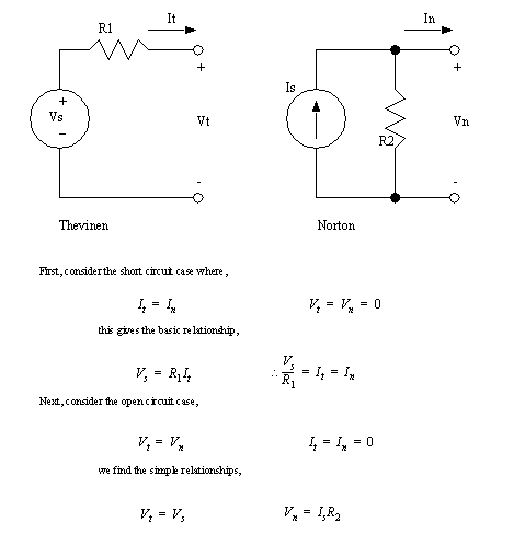
2.2 Thevinen and Norton Equivalents
• A sometimes useful transformation is based on the equivalence of certain circuit elements,
• We can use this to test an unknown circuit for open circuit voltage, and short circuit current, and then replace it with an equivalent circuit.
1. Measure open circuit voltage Vs
2. Measure short circuit current Is
3.a) If using a Thevenin equivalent calculate, Rs = Vs/Is
3.b) If using a Norton equivalent calculate, Rs = Vs/Is
4. Draw the appropriate circuit.
* note the resistor values are the same for both circuits.
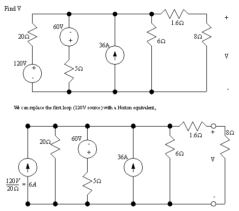
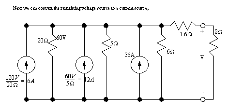
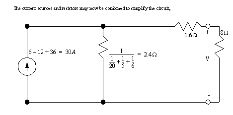
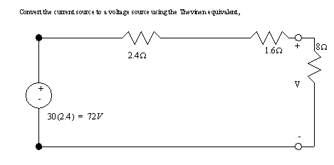
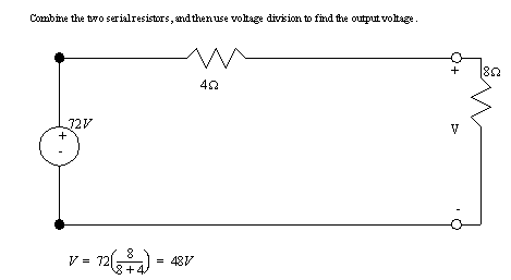
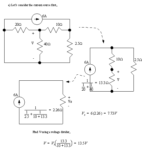
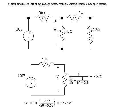
• We can also use the Thevenin/Norton transformation to simplify circuits. Consider example 4.13 from [Nilsson].
2.2.1 Superposition
• This is a simple technique that can be used when there are multiple sources in a circuit. The basic technique is,
1. Select one source in a circuit.
2. Make all other current sources open circuit.
3. Make all other voltage sources short circuits.
4. Analyze as normal.
5. Pick the next voltage/current source and go back to 2.
6. Add together the results for each source.
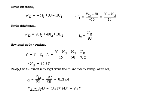
• Consider an example below, 4.19 from [Nilsson],
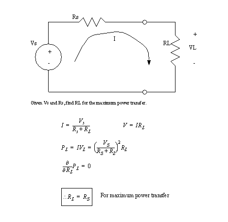
2.2.2 Maximum Power Transfer
• When we will add a load to a network, we may want to try and maximize the amount of power delivered to it.
• Consider the simple case below,
• For practice try proving this theorem for the Norton equivalent circuit.
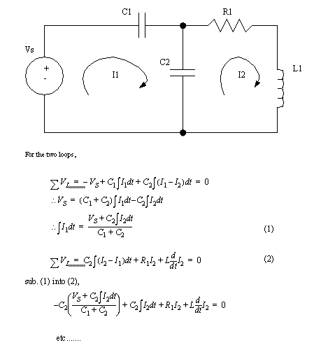
2.3 Circuits Containing Capacitors and Inductors
• When circuits contain capacitors, inductors, or other complex components, the solving techniques are the same. The main difference is that you will end up with differential expressions. (later we will see better techniques for dealing with these components)
• Consider the example,