
• Goal: To learn how to install the software
• Note: These instructions should lead you point by point, but pay attention to the details on the computer screen.
1. Turn on the computer, it will start to boot up. Once booted determine if the RSLogix 500 software is installed. If it is skip this section.
2. Examine the contents of the software box. There should be manuals for the software and the PLC. There should also be a CDROM and a floppy disk. You will also find quick reference cards, training information, etc.
3. Put the CDROM in the computer. A screen should automatically appear asking you to install the software. Click on the install button and the installation should begin.
5. After this install RS-Linx. This program will be handle communication between the ladder logic program and the PLC.
• Goal: To learn how to connect the PLC to the computer.
1. Open the PLC box and remove the manuals and PLC, or find the manuals on-line at http://www.ab.com. Examine both. Flip up the terminal strip covers and look at the labels.
2. Connect the provided power cord. Plug the PLC in, turn it on and look to see if the power light turns on. Turn off the PLC before the next step. NOTE: the power is wired directly to the PLC L1, L2/N and ground terminals on the front of the PLC.
3. The communication cable has two connectors. The round connector plugs into the front of the PLC: there is a small door on the left hand side. The other end of the cable should plug into the back of the computer. This will either be in ‘COM1’ or ‘COM2’. Chances are if there is a serial mouse attached to the computer, it will be ‘COM2’. If you are not sure, you can try both later.
4. Turn on the power. You should see the ‘power’ light go on. Other lights may also be on.
• Goal: To run the software and communicate with the PLC.
• Note: You should only need to do this the first time the software is set up.
1. Move the mouse to the bottom left corner of the screen to where the “Start” button is located and click once. Next, click on “Programs” then “Rockwell Software”, then “RSLogix 500 English”, and finally “RSLogix 500 English”.
2. This should start the RSLogix ladder logic programming software. A blank window should come up. It will be necessary to open a project before beginning to program.
3. Select ‘File’-’New’ and then select the processor ‘Micrologix 1000’. Next, change the driver to ‘AB_DF1-1’. This may cause the software to start the RS-Linx program: if it does go to step 4, if not go to step 5.
4. (If RS-Linx has started and is on the screen) Go to ‘Communications’-’Configure Drivers...’-’RS-232 DF1 Devices’-’Add New’. Pick the appropriate COM port and set the device to ‘micro/panelview’. Then select ‘Autoconfigure’. It should find the PLC and set the port appropriately. Click ‘OK’ and get the RSLogix software back.
5. Click ‘OK’ on the new file creation screen. The program will put up a project window. This will include a scrolling menu on the left that allows access to many functions of the PLC. The ladder logic will appear on the right hand side. At this point you are ready to enter some ladder logic.
• Goal: To set up a new project file and a simple program.
• Note: A separate project file is needed for each controller. If a controller has multiple programs, each one should have a project file.
1. A window will appear on the screen. On the right hand side is where ladder logic is entered and displayed. On the left are system settings. On the top are the controls used for programming and other functions.
2. Look carefully at the bar at the top of the screen. At the right hand side there are small symbols. Point to the left most symbol and hold down the left mouse button (keep it pushed for now). Drag the mouse down to the ladder logic window. A green box will appear, drag the mouse pointer to it and let the mouse button go. This should add an empty rung to the program.
3. Use the same method with the mouse to drag down a set of input contacts to the empty ladder rung.
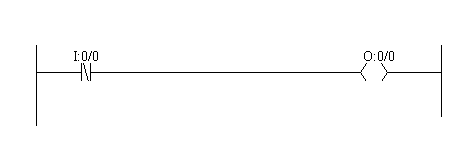
4. Now drag down an output coil to the ladder logic run so that it looks like the one below.
5. Now the names of the inputs and outputs will be added. For the input contact, double click with the left mouse button on the “?” above the input contact. Type in the value shown below and press return. Do the same for the output coil. Note: what is displayed will appear different from what was entered.
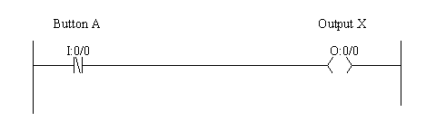
6. Right click on the input contacts and select “Edit Description: I:0/0”. Enter the description for the contact “Button A”. Do the same for the output coil so that it looks like the figure below.
‘A<ENTER>’, press <ESC> when done.
• Goal: To transfer a program to the PLC and run it.
1. At the top of the window select “Comms” then “Download”. You will be asked for a filename, enter ‘seminar’ for now. Later on you should give this a name related to the project.
2. You will be asked if you are sure you want to download, select “yes”. You may get a message that the SLC is in “RUN MODE”. If you select “Yes” the program in the PLC will stop running so that the new program can be downloaded. After the program is downloaded you will be asked if you want to switch back to “RUN” mode, select “Yes”.
3. When asked “Do you want to go Online?” select “Yes”. The screen will now show the actual state of PLC inputs and outputs. Turn on Input 0 to the PLC, and notice that the rung on the screen changes. It is also worth noticing that there is a slight delay between pushing the switch, and the change on the screen.
NOTE: After this point, keystrokes and menu choices will not be fully described.
• Goal: Enter and edit ladder logic with branches and add comments.
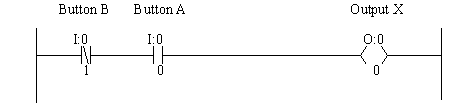
1. Start by disconnecting from the PLC by selecting “Comms”, then “Go Offline”. Edit the program to look like the program below by dragging down a normally open contact, and adding the numbers shown.
2. Download the program to the PLC and run it. Push buttons and see how it behaves.
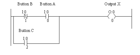
3. Go offline and add in the branch in the figure below. To do this drag down a branch icon from the bar above to a green box before the two input contacts. Then use the mouse to drag the other side of the branch (shown as a red box) to the other side of the input contacts.
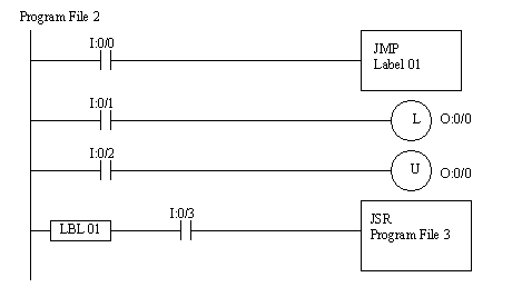
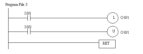
• Goal: To learn how latches work
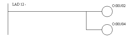
1. Go offline and enter the following ladder logic.
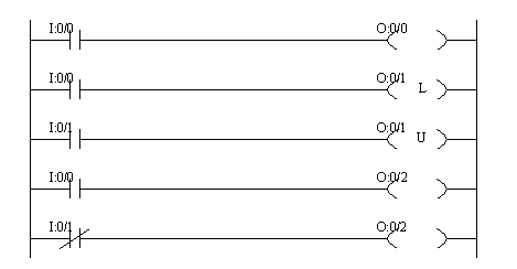
2. Download the ladder logic and observe how the switches change the operation of the latches. Notice that the second last line of ladder logic has no effect: this is because the output ‘O:0/2’ was used twice, and only the last use counts.
3. After a latch is set (O:0/1) turn off the PLC, and turn it back on. Do the latched outputs stay latched? The programming software will give an error message “Communications loss to processor“, just click “retry” to reconnect to the PLC.
• Goal: To learn how timers work
1. Go offline and enter the following ladder logic. The Timer function can be found by clicking on the “timer/counter” tab. You can return to the normal functions by clicking on the “user” tab.
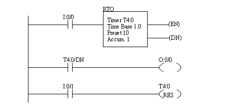
2. Run the ladder logic and observe how the switches change the operation of the timers. Try running the timer by switching the input on and off a few times while it is counting.
3. After running the timer turn the PLC off and on, does the output stay on?
4. Change the counter so that it takes 2 seconds to run by clicking on the “preset” on the timer and then entering “2”.
5. Change the time base to 0.01: you will need to go offline and download the program again. How does this change the operation of the timer?
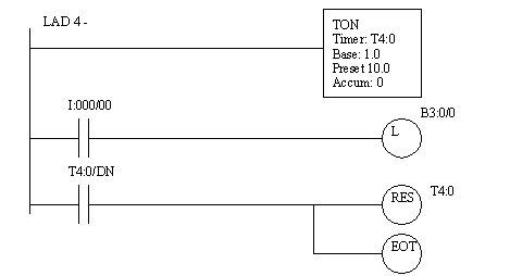
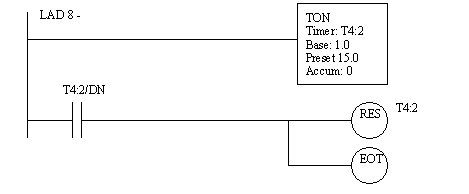
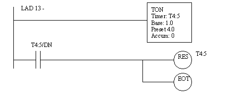
6. Edit the ladder diagram to use a “TON” timer, as shown below. You will have to go offline to do this. SHORTCUT: Click on the “RTO” on the top of the timer, and then type in “TON” instead.

7. Run the ladder logic. This time the input must stay on for a full 10 seconds before the output will turn on. How is this different from the “RTO”?
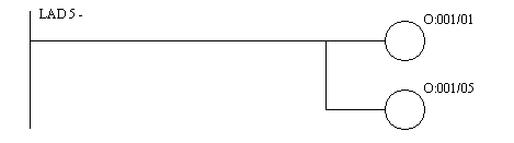
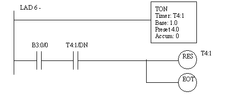
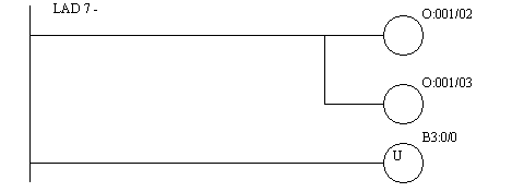
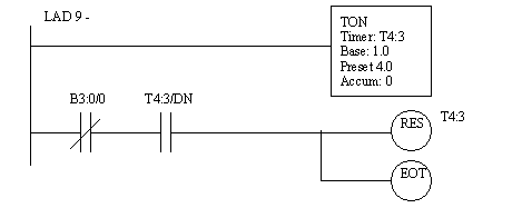
8. Edit the ladder diagram so that it looks like the diagram below.
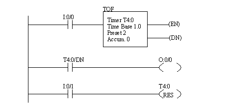
9. Run the ladder logic. This timer uses the switch turning off to start counting. Try pushing the switch a few times quickly then slowly.
• Goal: To learn how timers work
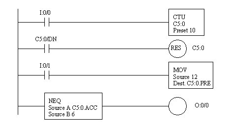
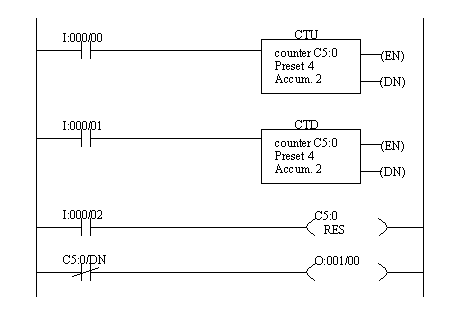
1. Enter to following ladder logic and observe how the switches change the operation of the counters. Does it match what was discussed earlier?
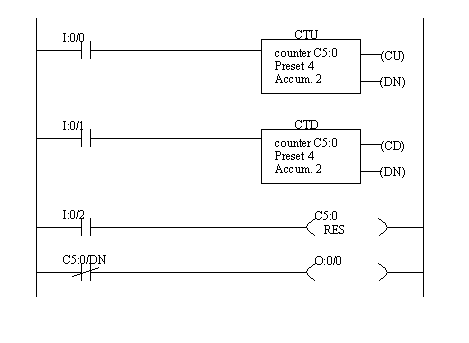
2. Modify the counter to count from 0 to 10.
• Goal: To see basic mathematical calculations
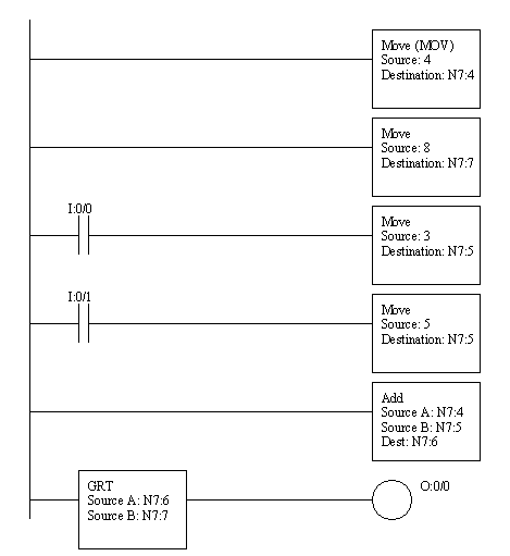
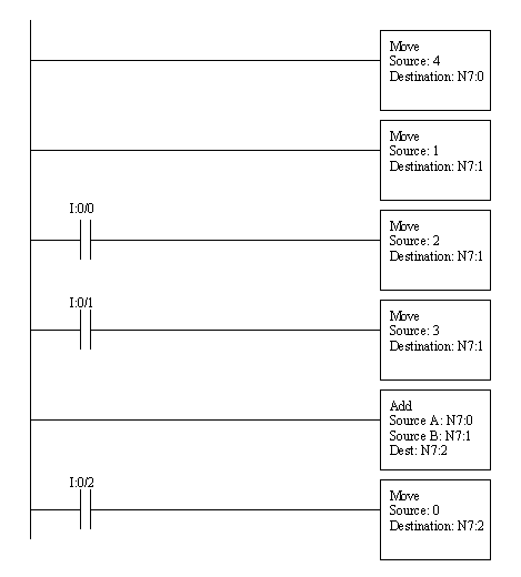
1. Now we will write a program that adds two numbers. If the sum is greater than 8 then an output will turn on. Enter the ladder logic and run the program. Watch the values displayed, and notice how inputs I:0/0 and I:0/1 change the values.
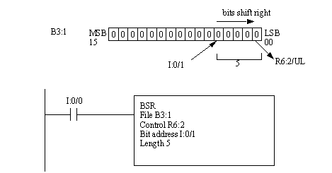
1. Run the software and start the off line programming module. Clear all of the memory and enter the following program.
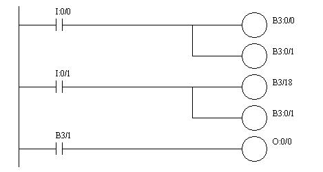
Note how the bit addresses changes. In particular B3:1/2 changed from the word format to the bit count format B3/18. The calculation is 1*16 + 2 = 18.
2. Download and run the program. In on-line programming mode, test the program to see how it behaves.
3. Next, look at the values in the memory of the PLC. First look at the left-hand side of the screen. One of the sections is labeled “Data Files”, under this there is “B3: Binary”. Double click on this one to bring up a display window.
1. Run the ladder logic program and enter the following ladder logic. Run the program and see what happens.
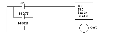
2.. Select the data file memory under “Data Files” as “T4:0”. Now press the input buttons and watch the values for T4:0 change.
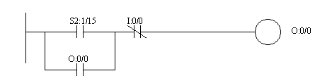
1. Under “Data Files” select “S2: Status” to display the status memory of the PLC. Look through and notice many of the values that are available. The values that are gray can only be written to, while the others can be set by on the screen or by a ladder logic program. Also notice that memory addresses are also provided.
2. Enter the following ladder logic. Notice that the first scan value ‘S2:1/15” has been recognized as the first pass value. Download and run the program. Turn off the PLC and repeat. Notice how the bit is only set when the PLC is turned on.
3. Go to “Database” then “Address/Symbol” and double click. This will bring up a list of labels for all of the IO points in the system, including those defined by the user, and predefined values such as status bits.
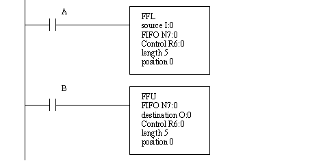
1. Enter the program below, and run it. Try pushing input buttons in different combinations and see what happens.
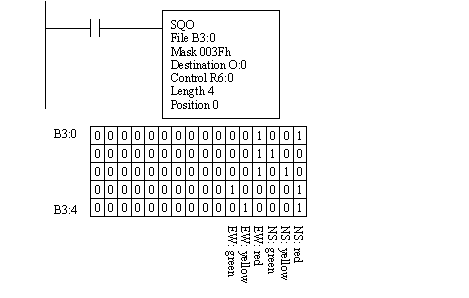
1. Enter and run the following ladder logic.
2. Modify the last ladder logic program to match the one below. Run the program.
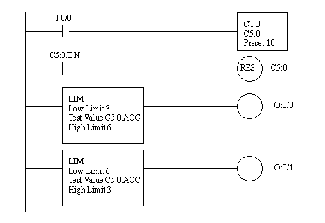
3. Write a program that uses the other types of comparison functions.
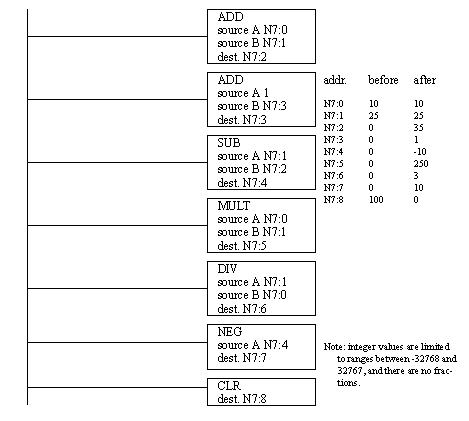
1. Enter and run the following program.
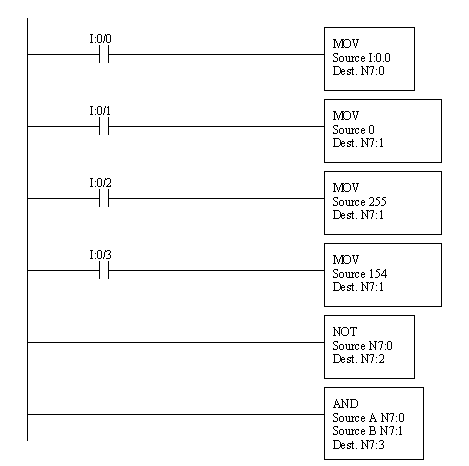
2. Try other Boolean logic functions in the previous program. Try changing the numbers written into N7:1.
1. Enter and run the following ladder logic.
2. Modify the previous program to make lights flash across the outputs (like Christmas tree lights).
1. Enter and run the program below.
1. Enter and run the program below.
1. Enter and run the programs below.
1. Examine the PLC rack. Flip up the covers at the top of the cards. Flip down the terminal strips on the front of the cards. The cards can now be removed: this will require a bit of force, but the levers at the tops of the cards will help. Write down the card numbers, and the rack number they will look something like ‘1771-OB1’)
2. Look at the backplane of the PLC chassis. There are various connectors and switches. At this time we want to set the switches on the backplane as shown below. These can also bee seen in the “Quick Start Guide”
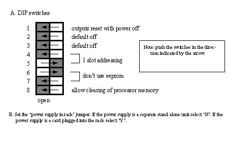
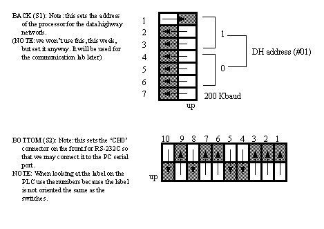
3. Look at the CPU card (PLC-5/11). Inside there are DIP switches that need to be set for communication parameters. (Look at the back of the CPU card and you will also find a legend for these switches.
4. Put the CPU card (only) back in the first slot in the rack. Turn the key to ‘rem’ for remote operation mode. Apply power and watch the status lights on the CPU. The ‘proc’ light should go on and stay a steady red, all other lights should be off. Have a look through the PLC5 quick start manual, pay extra attention to chapter 4.
5. Turn off the power and add a DC input card and DC output card to slots 0 and 1 (the order is not important, but write this down). Since we are using the 2 slot addressing mode these two slots will act like one, we refer to this as group 0. In total there are 8 slots, but in two slot addressing there are 4 groups. Each group has to have one input and one output card. This method allows us to have longer racks than normal. Apply power to the PLC and watch to see if the active light goes on (on the input card).
6. Turn off the PLC and plug the (null modem) RS-232 serial cable into the computer and the PLC ‘CH0’. Turn on the computer and PLC, and wait until Windows has finished loading.
7. Run the programming software ‘RSLogix 5 English’. A blank window should come up. It will be necessary to open a project before beginning to program. Another program, called RS-Linx’, will also be used to communicate with the PLC.
8. Select ‘File’-’New’ and add a processor ‘PLC-5/11’, give the series/revision ‘E’, and give the ‘Processor Name’ a unique identifier. Next, change the driver to ‘AB_DF1-1’. This may cause the software to start the RS-Linx program: if it does go to step 9, if not go to step 10.
9. (If RS-Linx has started and is on the screen) Go to ‘Communications’-’Configure Drivers...’-’RS-232 DF1 Devices’-’Add New’. Pick the appropriate COM port and set the device to ‘SLC-CH0’. Then select ‘Autoconfigure’. It should find the PLC and set the port appropriately. Click ‘OK’ and get the RSLogix software back.
10. Click ‘OK’ on the new file creation screen. The program will put up a project window. This will include a scrolling menu on the left that allows access to many functions of the PLC. The ladder logic will appear on the right hand side. Next, we want to set up the PLC configuration. Select ‘IO Configuration’ and change the ‘chassis type’ to the type you wrote down earlier. Change the ‘Rack addressing’ to ‘2 slot’. Finally, change the cards in the rack to match the cards you added (click on the leftmost ‘chassis’ item). At this point the PLC layout should be complete.
11. Now we can begin to enter ladder logic. To do this click on the line number box that says ‘0000’ and hit return: a new blank line of ladder logic should have been created. Move up to the icon bar that contains ladder logic symbols and select a normally open input contact: it should appear on the blank line. Enter the address ‘I:000/00’ to indicate the input card ‘I:’ on rack ‘0’ and group ‘0’ and input bit ‘/00’. Click on an output symbol and this should add an output to the ladder line. Enter the address ‘O:001/00’ to indicate the output card ‘O:’ for rack ‘0’ and group ‘0’ and output bit ‘/00’. (Note: because we are using two slot addressing the input and output cards are in two separate slots, but share the same group)
12. We are now ready to download and test the program. Go to the ‘Comms’-’Download’ option. Answer the questions as required, and the program should start to download. You may be asked if you want to go on-line, answer yes. If the PLC is running you will see the ‘proc’ light turn green.
13. Connect a 12V DC power supply to the common and input ‘00’ on the DC input card. You should see the input light go on. The ladder logic program should make the output ‘00’ on the output card also go on.
14. Use the ‘help’ button to search for a topic of interest.
15. Enter the ladder logic below, and test it using the 12V DC power supply.
16. Try entering ladder logic from a previous tutorial or lab that uses a timer. (Note: You will need to adapt it to the new addresses on the PLC.)
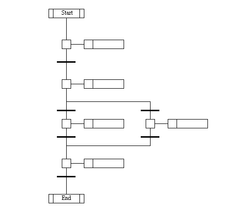
17. Flip through the “Getting Results with RSLogix5” book, and notice the general topics mentioned. Use the help screens to look up more information on various topics. Look for SFCs.
18. Now we will create an SFC. First, we need to close the current file and start a new one. Now, highlight the “Program Files” item on the main program screen. Click the right mouse button and select “SFC”. Enter program “1” (not 3), select “SFC File”, and name the file something unique. If you click “OK” then the program will be created and added to the project tree.
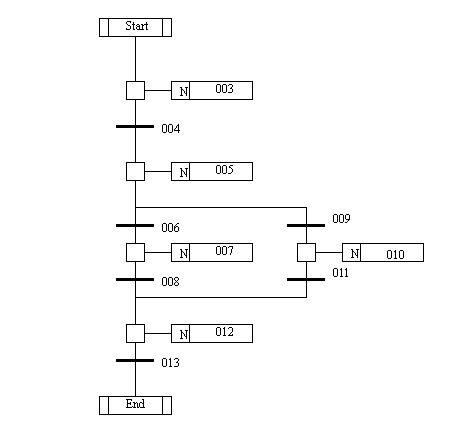
19. Open up the SFC edit window by double clicking on the “SFC” program file. The SFC edit window appears to the right and can be modified. Edit the program to look like the one below: don’t worry about the contents just yet, but the form of the diagram must be the same.
20. When done entering the diagram use “Edit”: “Verify SFC Chart”. The SFC diagram will now be replaced with something like the one below. Notice that ladder logic programs have been created. The numbers on the SFC diagram are related to the new ladder logic numbers. We will modify the ladder logic for each step and transition next.
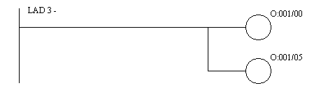
21. Double click on “Program Files”: “LAD 3-” and the SFC diagram will disappear and a ladder diagram will appear. This ladder corresponds to the first step in the SFC. So, here we want to do the actions required using ladder diagrams. Enter the ladder logic below for the program files.
22. Run the program: You should see a traffic light configuration. With input ‘00’ changing the length of the green light.
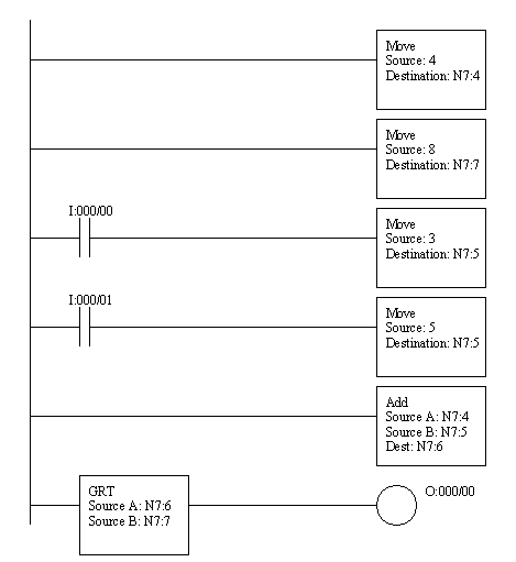
23. Finally we will write a program that adds two numbers. If the sum is greater than 8 then an output will turn on. Enter the ladder logic and run the program. Watch the values displayed, and notice how applied voltages to inputs ‘00’ and ‘01’ change the values.
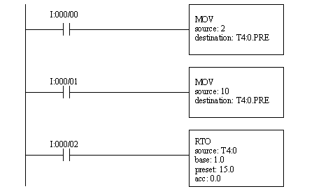
24. Enter and try the following program, it will directly influence timer preset values in memory. Try testing the basic operation. Then, set the preset to 2 seconds. Then cause the timer to pass the 2 second preset, note the result, but don’t reset the timer. Set the preset to 10 seconds, and continue the timer increment.
1. Enter and run the program below.
1. Enter and run the following ladder logic.
1. Write your own program to average the time that an input is held on. Use a timer to find the time the button is held. Add comments to the rungs and symbols to the inputs and outputs.
SoftLogix 5800: We will be using a PC as our main PLC
network communication may be hindered by Windows firewall
the soft PLCand networking is very sensitive to computer timing, shut down programs not needed.
1. (If not already done) Set up the rack as shown below. The cards are designed to be installed from left to right.
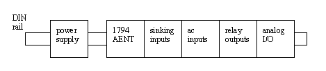
2. Refer to the manuals for the hardware on the Allen Bradley web site. Note that the installation guides only provide mechanical and wiring information. The Users Manuals will be useful when programming.
3. (If not already done) Wire the rack as shown below. When done have the wiring checked by an instructor.
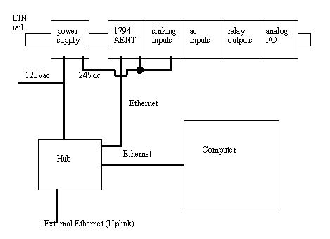
4. Plug in the rack and check for a steady green ‘module status’ light. This will indicate that the module is generally operating correctly. Check the lights on the hub for correct operation.
5. If not already operating, start the computer. If the computer was already running you may need to restart the network connection. Use a web browser to verify the network connection.
6. Set up the hub for the following settings,
1. (If a virtual machine is being used start it now). The SoftLogix rack monitor should be running, If not, you may start it by clicking on the icon on the task bar that looks like XXXXXXXX. This program sets up a virtual PLC rack. Slot 0 will probably contain RSLinx, this will handle communication between all of the PLC programming software. If there are cards in any other slots remove them.
2. Right-click on slot 2 and select ‘Create’. Choose “Softlogix EthernetIP XXXX” then ‘OK’. This will add a bridge between the software based PLC (not created yet) and the networked I/O. add the following settings and use ‘next’ and ‘finish’ as needed.
3. Right-click on slot 1 and select “Softlogix 5860-L60” then OK. This will create the software based PLC processor.
4. Notice that there are status lights to track the condition of the processor and network cards. These will become very useful when diagnosing problems later.
4. When the Softlogix processor is ‘inserted’ RSLinx will start, if not already running. Use the RS-Who function to check and see what drivers are loaded. If “AB_VBP-1” or “ETH-XXX” Does not exist, add it using “Configure Drivers”.
1. Run “RSNetworx for Ethernet/IP”. This program will identify and browse network components.
2. Select “File” then “Ethernet/IP”.
3. “Network”, “Upload from Network”. Select “Ethernet/IP” in the RSLinx window when it pops up. Save the network as “Ethernet.enet”
4. Do the same for the “5860 Ethernet IP Processor”.
5. use browse to identify devices
3. To scan for device level issues use “Network” then “Online”
1. Run “RSLogix 5000 Enterprise Series”. Create a new project using “File” then “New”. This will bring up a “New Controller” window. Enter the following settings then select ‘OK’.
2. A new set of project windows is created. On the left side are general settings, including tags.
3. First we will add some I/O. Near the bottom left is a tab labelled “I/O Configuration”. Right-click and select “New Module”. Select “Ethernet/IP” then OK. Enter the following settings and use ‘next’ and ‘finish’ as necessary.
4. In the previous step we have indicated that we are using the network, but not what we are talking to. Right-click on the device just created and add a “1794-AENT/A Twisted Pair” adaptor with the following settings.
6. At this point all of the I/O values are defined. Next we can define our tags (Variable names). To do this click on the XXXXXXX on the upper
7. At long last we are now ready to write our first program. Enter the following ladder logic under the ‘Main Program’ and then download it to the processor.

8. Once downloaded, check the processor and verify that the ‘Run’ and ‘IO’ lights are on steadily. This will indicate that the program is running. The lights on the face of the Ethernet IO rack should also be green. (note: red is bad).
NOTE: The camera is not required for this tutorial.
1. If the ‘Framework’ software is not installed, install it from the CD.
2. A window will appear called ‘PC Communications’. Select ‘Emulator’ then ‘Model 630’. Two windows should now be on the screen. The window called ‘DVT FRAMEWORK’ is the main programming software. The window titled ‘DVT SmartImage Sensor Emulator’ takes the place of an actual camera for tutorials like this one.
3. First we need to load images into the emulator window. To do this select ‘Configure’, then ‘Image Sequence...’. An ‘Image Sequence Configuration’ window will appear. Use ‘Browse for images’ and select the first image as ‘Image001.bmp’ and the last image as ‘Image008.bmp’. Then select ‘OK’ to load the images.
4. In the Framework window select the ‘Products’ then ‘Products Management’. Select ‘New’ and enter ‘tutorial’ as the product name. This will be used to store one or more tests for a particular product. Note: if the camera is to be used to test multiple types of products, the names of other products will also be entered here. Select ‘OK’ to dismiss the window.
5. We can now start the camera running. In the top toolbar there is a black triangle that points to the right (near a red circle). Click this to run the camera emulator.
6. Select a sensor for the product on the left side with ‘EdgeCount’. On the palette that appears select a line draw it so that it covers the circle. Select ‘OK’ and the tests should begin. The test status line will show the number of edges detected in the image.