23. Lab 4: Deadband Compensation for Bidirectional MotionTo compensate for ’stiction’ in a bidirectional open loop controller. Friction in motors will prevent them from turning when small voltages are applied. This effect is normally known as ’stiction’, a combination of the words static and friction. Friction is present in all motors, however this effect is greater in lower cost motors. When a motor is connected to a mechanical system the friction may increase greatly. In most cases we can reduce the cost of a new design by using less expensive motors and compensating for larger friction effects in software. In motors there are two types of friction that must be considered. The static friction, ’stiction’, will prevent initial motion. If the motor supplies enough torque to break free and start turning, the kinetic friction will provide a roughly constant friction torque. Figure 23.1 Motor deadband for a bidirectional motor shows an example of how this friction affects the relationship between the voltage applied to a motor, and the resulting velocity. At very low voltages the torque is too low to overcome the stiction. The region where the applied voltage has no effect is called the deadband. Once the applied voltage exceeds the deadband limits the motor will start to turn. While turning, the motor experiences kinetic friction, damping and other effects. If the voltage supplied to the motor is slowly decreased it will eventually ’stick’. However, the sticking force will be lower than the static friction force. This alternate path is shown in the figure as a heavy dashed line. 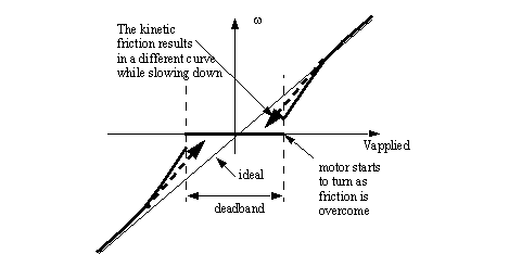
Figure 23.1 Motor deadband for a bidirectional motor There are a number of methods for compensating for a non-linear deadband in a system. A simple method is shown in Figure 23.2 Deadband approximation for a bidirectional motor. This method involves finding the voltages where the motor breaks free in the positive and negative directions. These are used in a program to change the wanted output voltage, to an adjusted output voltage. 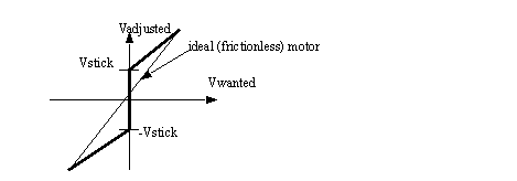
Figure 23.2 Deadband approximation for a bidirectional motor The equations to implement a deadband compensator are shown in Figure 23.3 Deadband approximation for a bidirectional motor. These adjust the wanted voltage to exclude the deadband. In this case the equations also adjust the relationship to allow the full use of the PWM output scale. 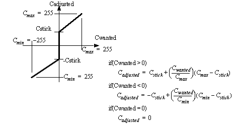
Figure 23.3 Deadband approximation for a bidirectional motor The equations from the previous example are implemented in the subroutine given in Figure 23.4 Deadband compensation for an ATMega32 controlled output. This subroutine actually allows the positive and negative deadband limits to be different, as would be expected in an actual motor. The subroutine also verifies that the corrected values are within the limits of the PWM output. In the example the equations have been rearranged to prevent roundoff errors during the integer calculations. The moving variable must be set so that when the velocity of the system is approaximately zero, it will have a value of 1. The algorithm includes an option to apply a higher (static) torque when not moving (moving == 0) to ’break away’. Normally this would be used for a short period of time to allow the motor to start moving, and then be reduced (moving = 1) so that the kinetic friction torque is used. If a system has feedback the detection of motion can be used to change the coefficient used. 
Figure 23.4 Deadband compensation for an ATMega32 controlled output Limiting function are used when the requested output exceeds the available output range. An example is shown in Figure 23.5 An output limiter. 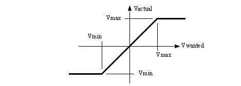
In previous labs we used a transistor to control motor movement in one direction. The H-bridge circuit shown in Figure 23.6 H-bridge circuit for motor control can be used to drive a motor in two directions. As before, the transistors are used to switch current flow. In this case applying a voltage to the A1 and A2 terminals would allow voltage to flow left-to-right through the motor. Turning on inputs B1 and B2 would cause current to flow right-to-left through the motor. When the inputs are controlled using a PWM signal the effective motor voltage can be varied. 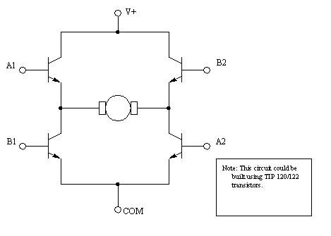
Figure 23.6 H-bridge circuit for motor control When controlling an H-bridge some extra logic circuitry is commonly used, such as that in Figure 23.7 H-bridge control logic. The main purpose for this circuitry is to protect the H-bridge. For example, if A1 and B1 were both on at the same time, current would bypass the motor, on the left side. The current would be high, similar to a short circuit, eventually destroying the devices. The logic in the figure prevents this. In the logic the PWM output is connected to the E (enable) input. The direction is then used to determine which pair of transistors is turned on. 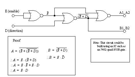
Figure 23.7 H-bridge control logic In this lab we will use an integrated circuit that already contains protection circuitry. For our purposes we can approximate the control logic in that chip with that in Figure 23.8 H-bridge control logic. In this logic we will apply the PWM signal to the E (enable) input. We will then turn on the CW (clockwise) or CCW (counter clockwise) output to determine direction. Care is required to avoid turning both the CW and CCW outputs at the same time. 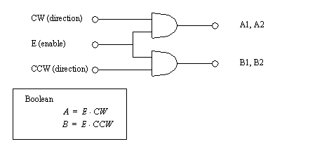
Figure 23.8 H-bridge control logic As you will recall from previous labs the PWM output range is from 0 to 255. However for bidirectional motion we will have both positive and negative motor outputs. The program in Figure 23.9 Subroutines for PWM outputs and reversing the motor direction is designed to compensate for this by checking the sign of the requested output value. Depending upon the sign the CW and CCW outputs will be switched, and the negative values made positive. This routine also checks to make sure that the values don’t exceed the maximum limit of 255. This subroutine also changes the direction of rotation by reversing two of the output bits on port C. 
Figure 23.9 Subroutines for PWM outputs and reversing the motor direction The subroutines in Figure 23.10 The output update subroutines deal with general IO updates, as well as a simple delay routine. It allows the deadband compensation to be disabled to simplify the identification of deadband limits. 
Figure 23.10 The output update subroutines The main program is shown in Figure 23.11 The main test program. It includes numerous keystroke commands to allow the modification of settings. 
Figure 23.11 The main test program 1. Develop a program for open loop velocity control using the subroutines given in the theory section. The program should compensate for the deadband of the motor, as described in the prelab. The main program should initialize the PWM routines and other outputs and allow keyboard inputs to change the setpoint. The routines that correct for the deadband stiction and update the PWM output are not part of an interrupt driven subroutine. This is because we are using feedforward control and there is no feedback value available to update the system. 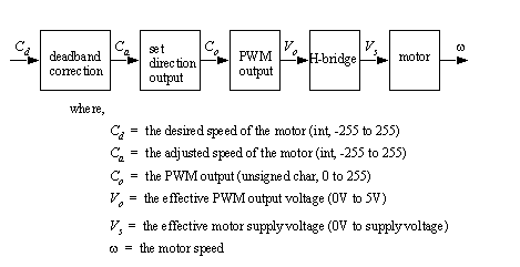
Figure 23.12 The open-loop controller 2. Develop a plan for measuring the deadband limits for multiple motors. computer with the winavr compiler and megaload ATMega32 board including an L293D Push-pull four channel driver 1. Set up the motor controller as shown in Figure 23.13 Using an ATMega32 motor controller with a L293Ddriver, the pins for the device are shown in Figure 23.13 Using an ATMega32 motor controller with a L293Ddriver and Figure 23.14 L293D pinout diagram (top view). The L293D actually contains four drivers, or the equivalent of two H-bridges. In this case we will use two of these that can supply a peak current of 600mA. 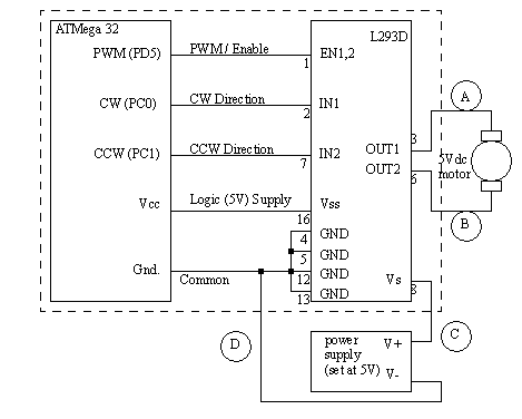
Figure 23.13 Using an ATMega32 motor controller with a L293Ddriver 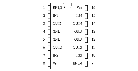
Figure 23.14 L293D pinout diagram (top view) 2. Enter the program developed for the prelab and test the motor controller. 3. Run the program with the deadband correction disabled. Vary the voltages for the motor to fall between -255 and 255 and record the desired motor speed, the output voltage and the actual motor speed in a table. Note: that the negative values are probably shown as 2’s compliment negative value and must be converted to positive values. 4. Use the data collected in the previous step to determine the deadband limits, and enable the deadband compensation in the program. 5. Repeat the readings taken in step 3 with the deadband values enabled. 6. Compare the results with and without deadband compensation on a graph. Plot the values using voltages instead of the PWM values. 7. Repeat the process for at least two other types of DC motors. 8. By now you will have observed that even with deadband compensation the motors may still ’sick’ at very low speeds. One trick to overcome this issue is to add a brief ’kick’ at the start of a speed increase. Do this by adding some code similar to that shown in Figure 23.15 ’Kick’ code: please note you will need to modify this somewhat. 
|