12. PLC5 Tutorials
12.1 A-B PLC-5 CPUs with RSLogix and RSLinx Programming Software
12.1.1 Basic PLC-5 Setup
1. Examine the PLC rack. Flip up the covers at the top of the cards. Flip down the terminal strips on the front of the cards. The cards can now be removed: this will require a bit of force, but the levers at the tops of the cards will help. Write down the card numbers, and the rack number they will look something like ‘1771-OB1’)
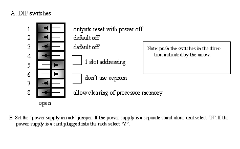
2. Look at the backplane of the PLC chassis. There are various connectors and switches. At this time we want to set the switches on the backplane as shown below. These can also bee seen in the “Quick Start Guide”
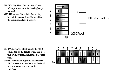
3. Look at the CPU card (PLC-5/11). Inside there are DIP switches that need to be set for communication parameters. (Look at the back of the CPU card and you will also find a legend for these switches.
4. Put the CPU card (only) back in the first slot in the rack. Turn the key to ‘rem’ for remote operation mode. Apply power and watch the status lights on the CPU. The ‘proc’ light should go on and stay a steady red, all other lights should be off. Have a look through the PLC5 quick start manual, pay extra attention to chapter 4.
5. Turn off the power and add a DC input card and DC output card to slots 0 and 1 (the order is not important, but write this down). Since we are using the 2 slot addressing mode these two slots will act like one, we refer to this as group 0. In total there are 8 slots, but in two slot addressing there are 4 groups. Each group has to have one input and one output card. This method allows us to have longer racks than normal. Apply power to the PLC and watch to see if the active light goes on (on the input card).
6. Turn off the PLC and plug the (null modem) RS-232 serial cable into the computer and the PLC ‘CH0’. Turn on the computer and PLC, and wait until Windows has finished loading.
7. Run the programming software ‘RSLogix 5 English’. A blank window should come up. It will be necessary to open a project before beginning to program. Another program, called RS-Linx’, will also be used to communicate with the PLC.
8. Select ‘File’-’New’ and add a processor ‘PLC-5/11’, give the series/revision ‘E’, and give the ‘Processor Name’ a unique identifier. Next, change the driver to ‘AB_DF1-1’. This may cause the software to start the RS-Linx program: if it does go to step 9, if not go to step 10.
9. (If RS-Linx has started and is on the screen) Go to ‘Communications’-’Configure Drivers...’-’RS-232 DF1 Devices’-’Add New’. Pick the appropriate COM port and set the device to ‘SLC-CH0’. Then select ‘Autoconfigure’. It should find the PLC and set the port appropriately. Click ‘OK’ and get the RSLogix software back.
10. Click ‘OK’ on the new file creation screen. The program will put up a project window. This will include a scrolling menu on the left that allows access to many functions of the PLC. The ladder logic will appear on the right hand side. Next, we want to set up the PLC configuration. Select ‘IO Configuration’ and change the ‘chassis type’ to the type you wrote down earlier. Change the ‘Rack addressing’ to ‘2 slot’. Finally, change the cards in the rack to match the cards you added (click on the leftmost ‘chassis’ item). At this point the PLC layout should be complete.
11. Now we can begin to enter ladder logic. To do this click on the line number box that says ‘0000’ and hit return: a new blank line of ladder logic should have been created. Move up to the icon bar that contains ladder logic symbols and select a normally open input contact: it should appear on the blank line. Enter the address ‘I:000/00’ to indicate the input card ‘I:’ on rack ‘0’ and group ‘0’ and input bit ‘/00’. Click on an output symbol and this should add an output to the ladder line. Enter the address ‘O:001/00’ to indicate the output card ‘O:’ for rack ‘0’ and group ‘0’ and output bit ‘/00’. (Note: because we are using two slot addressing the input and output cards are in two separate slots, but share the same group)
12. We are now ready to download and test the program. Go to the ‘Comms’-’Download’ option. Answer the questions as required, and the program should start to download. You may be asked if you want to go on-line, answer yes. If the PLC is running you will see the ‘proc’ light turn green.
13. Connect a 12V DC power supply to the common and input ‘00’ on the DC input card. You should see the input light go on. The ladder logic program should make the output ‘00’ on the output card also go on.
14. Use the ‘help’ button to search for a topic of interest.
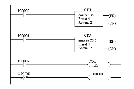
15. Enter the ladder logic below, and test it using the 12V DC power supply.
16. Try entering ladder logic from a previous tutorial or lab that uses a timer. (Note: You will need to adapt it to the new addresses on the PLC.)
12.1.2 Sequential Function Charts (SFCs)
1. Flip through the “Getting Results with RSLogix5” book, and notice the general topics mentioned. Use the help screens to look up more information on various topics. Look for SFCs.
2. Now we will create an SFC. First, we need to close the current file and start a new one. Now, highlight the “Program Files” item on the main program screen. Click the right mouse button and select “SFC”. Enter program “1” (not 3), select “SFC File”, and name the file something unique. If you click “OK” then the program will be created and added to the project tree.
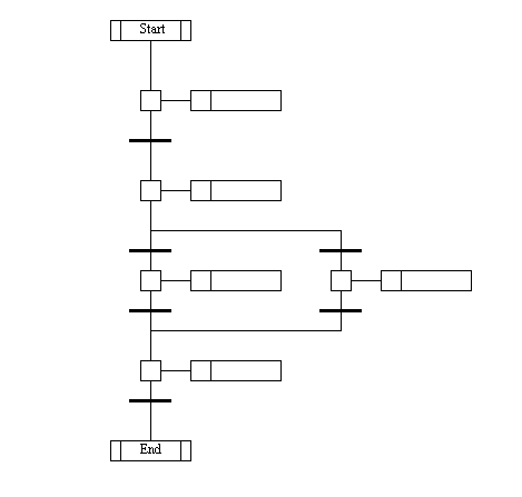
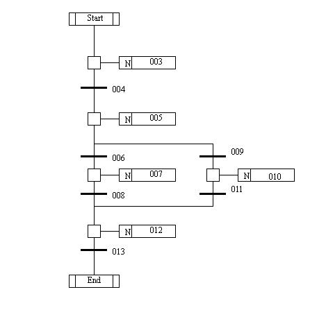
3. Open up the SFC edit window by double clicking on the “SFC” program file. The SFC edit window appears to the right and can be modified. Edit the program to look like the one below: don’t worry about the contents just yet, but the form of the diagram must be the same.
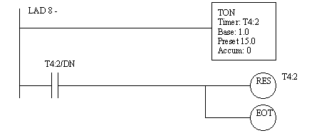
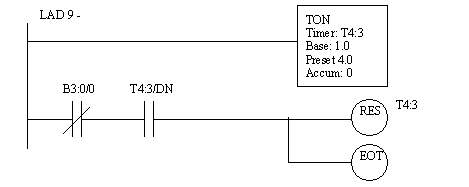
4. When done entering the diagram use “Edit”: “Verify SFC Chart”. The SFC diagram will now be replaced with something like the one below. Notice that ladder logic programs have been created. The numbers on the SFC diagram are related to the new ladder logic numbers. We will modify the ladder logic for each step and transition next.
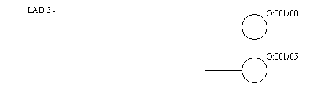
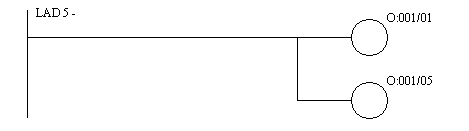
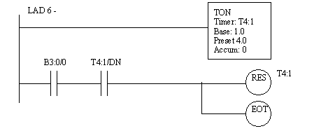
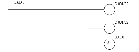
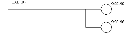
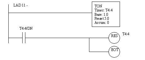
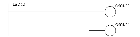
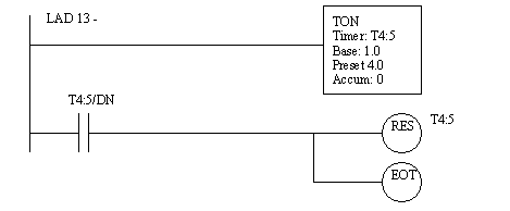
5. Double click on “Program Files”: “LAD 3-” and the SFC diagram will disappear and a ladder diagram will appear. This ladder corresponds to the first step in the SFC. So, here we want to do the actions required using ladder diagrams. Enter the ladder logic below for the program files.
6. Run the program: You should see a traffic light configuration. With input ‘00’ changing the length of the green light.
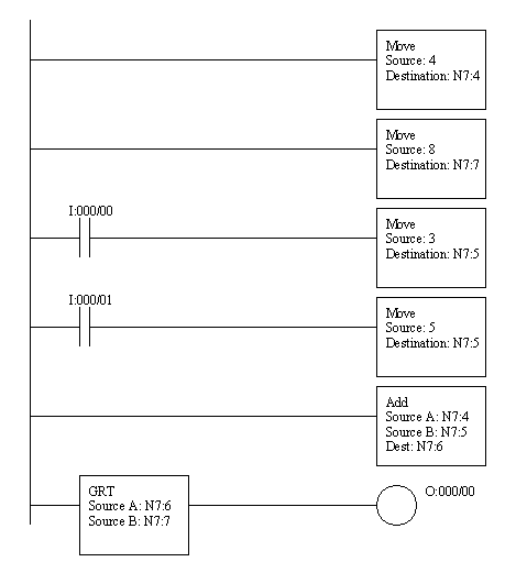
7. Finally we will write a program that adds two numbers. If the sum is greater than 8 then an output will turn on. Enter the ladder logic and run the program. Watch the values displayed, and notice how applied voltages to inputs ‘00’ and ‘01’ change the values.
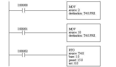
8. Enter and try the following program, it will directly influence timer preset values in memory. Try testing the basic operation. Then, set the preset to 2 seconds. Then cause the timer to pass the 2 second preset, note the result, but don’t reset the timer. Set the preset to 10 seconds, and continue the timer increment.
12.1.3 Math Functions
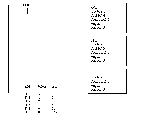
1. Enter and run the program below.
12.1.4 File Algebra
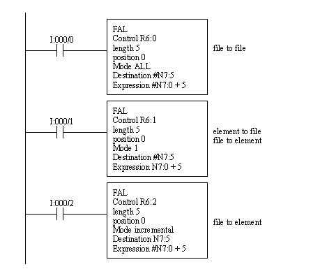
1. Enter and run the following ladder logic.
12.1.5 Individual Exercise
1. Write your own program to average the time that an input is held on. Use a timer to find the time the button is held. Add comments to the rungs and symbols to the inputs and outputs.