35. Industrial Robotics
• The nice definition (by the Robot Institute of America): “A robot is a reprogrammable multifunctional manipulator designed to move material, parts, tools, or specialized devices through variable programmed motions for the performance of a variety of tasks”
• The not-so-nice definition: Robots are one armed, blind, stupid, deaf, mute, and cannot feel and understand what they are doing.
35.0.1 Basic Terms
Links and Joints: Links are the solid structural members of a robot, and joints are the movable couplings between them.
Degree of Freedom (dof): Each joint on the robot introduces a degree of freedom. Each dof can be a slider, rotary, or other type of actuator. Robots typically have 5 or 6 degrees of freedom. 3 of the degrees of freedom allow positioning in 3D space, while the other 2or 3 are used for orientation of the end effector. 6 degrees of freedom are enough to allow the robot to reach all positions and orientations in 3D space. 5 dof requires a restriction to 2D space, or else it limits orientations. 5 dof robots are commonly used for handling tools such as arc welders.
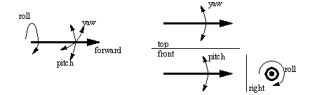
Orientation Axes: Basically, if the tool is held at a fixed position, the orientation determines which direction it can be pointed in. Roll, pitch and yaw are the common orientation axes used. Looking at the figure below it will be obvious that the tool can be positioned at any orientation in space. (imagine sitting in a plane. If the plane rolls you will turn upside down. The pitch changes for takeoff and landing and when flying in a crosswind the plane will yaw.)
Position Axes: The tool, regardless of orientation, can be moved to a number of positions in space. Various robot geometries are suited to different work geometries. (more later)
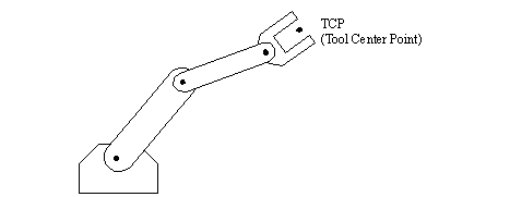
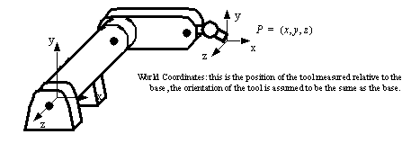
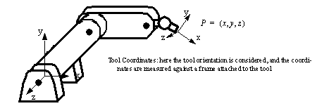
Tool Center Point (TCP): The tool center point is located either on the robot, or the tool. Typically the TCP is used when referring to the robots position, as well as the focal point of the tool. (e.g. the TCP could be at the tip of a welding torch) The TCP can be specified in Cartesian, cylindrical, spherical, etc. coordinates depending on the robot. As tools are changed we will often reprogram the robot for the TCP.
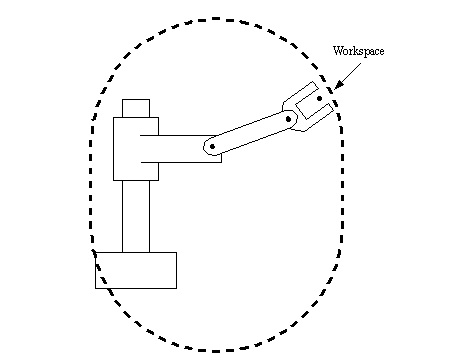
Work envelope/Workspace: The robot tends to have a fixed, and limited geometry. The work envelope is the boundary of positions in space that the robot can reach. For a cartesian robot (like an overhead crane) the workspace might be a square, for more sophisticated robots the workspace might be a shape that looks like a ‘clump of intersecting bubbles’.
Speed: refers either to the maximum velocity that is achievable by the TCP, or by individual joints. This number is not accurate in most robots, and will vary over the workspace as the geometry of the robot changes (and hence the dynamic effects). The number will often reflect the maximum safest speed possible. Some robots allow the maximum rated speed (100%) to be passed, but it should be done with great care.
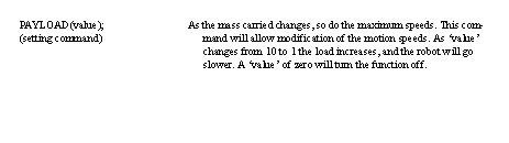
Payload: The payload indicates the maximum mass the robot can lift before either failure of the robots, or dramatic loss of accuracy. It is possible to exceed the maximum payload, and still have the robot operate, but this is not advised. When the robot is accelerating fast, the payload should be less than the maximum mass. This is affected by the ability to firmly grip the part, as well as the robot structure, and the actuators. The end of arm tooling should be considered part of the payload.
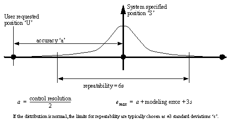
Repeatability: The robot mechanism will have some natural variance in it. This means that when the robot is repeatedly instructed to return to the same point, it will not always stop at the same position. Repeatability is considered to be +/-3 times the standard deviation of the position, or where 99.5% of all repeatability measurements fall. This figure will vary over the workspace, especially near the boundaries of the workspace, but manufacturers will give a single value in specifications.
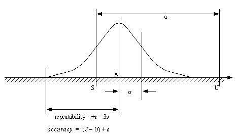
Accuracy: This is determined by the resolution of the workspace. If the robot is commanded to travel to a point in space, it will often be off by some amount, the maximum distance should be considered the accuracy. This is an effect of a control system that is not necessarily continuous.
Settling Time: During a movement, the robot moves fast, but as the robot approaches the final position is slows down, and slowly approaches. The settling time is the time required for the robot to be within a given distance from the final position.
Control Resolution: This is the smallest change that can be measured by the feedback sensors, or caused by the actuators, whichever is larger. If a rotary joint has an encoder that measures every 0.01 degree of rotation, and a direct drive servo motor is used to drive the joint, with a resolution of 0.5 degrees, then the control resolution is about 0.5 degrees (the worst case can be 0.5+0.01).
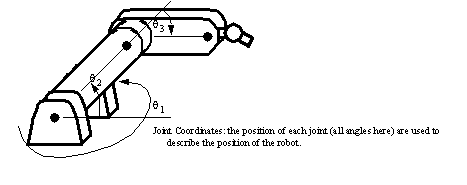
Coordinates: The robot can move, therefore it is necessary to define positions. Note that coordinates are a combination of both the position of the origin and orientation of the axes.
35.1 Positioning Concepts
35.1.1 Accuracy and Repeatability
• The accuracy and repeatability are functions of,
resolution- the use of digital systems, and other factors mean that only a limited number of positions are available. Thus user input coordinates are often adjusted to the nearest discrete position.
kinematic modeling error: the kinematic model of the robot does not exactly match the robot. As a result the calculations of required joint angles contain a small error.
calibration errors: The position determined during calibration may be off slightly, resulting in an error in calculated position.
random errors: problems arise as the robot operates. For example, friction, structural bending, thermal expansion, backlash/slip in transmissions, etc. can cause variations in position.
• Accuracy,
“How close does the robot get to the desired point”
This measures the distance between the specified position, and the actual position of the robot end effector.
Accuracy is more important when performing off-line programming, because absolute coordinates are used.
• Repeatability
“How close will the robot be to the same position as the same move made before”
A measure of the error or variability when repeatedly reaching for a single position.
This is the result of random errors only
repeatability is often smaller than accuracy.
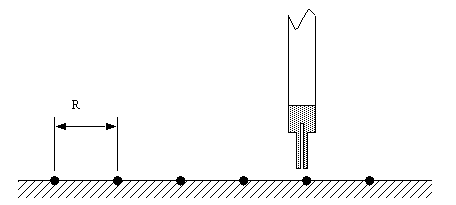
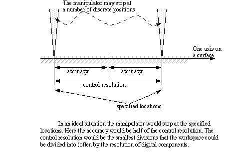
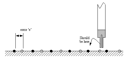
• Resolution is based on a limited number of points that the robot can be commanded to reach for, these are shown here as black dots. These points are typically separated by a millimeter or less, depending on the type of robot. This is further complicated by the fact that the user might ask for a position such as 456.4mm, and the system can only move to the nearest millimeter, 456mm, this is the accuracy error of 0.4mm.
• In a perfect mechanical situation the accuracy and control resolution would be determined as below,
• Kinematic and calibration errors basically shift the points in the workspace resulting in an error ‘e’. Typically vendor specifications assume that calibration and modeling errors are zero.
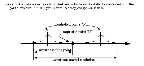
• Random errors will prevent the robot from returning to the exact same location each time, and this can be shown with a probability distribution about each point.
• The fundamental calculations are,
35.1.2 Control Resolution
• Spatial resolution is the smallest increment of movement into which the robot can divide its work volume. Spatial resolution depends on two factors: the systems control resolution and the robots mechanical inaccuracies. It is easiest to conceptualize these factors in terms of a robot with 1 degree of freedom.
• Control resolution: is determined by the robot’s position control system and its feedback measurement system. It is the controllers ability to divide the total range of movement for the particular joint into individual increments that can be addressed in the controller. The increments are sometimes referred to as “addressable parts”. The ability to divide the joint range into increments depends on the bit storage capacity in the control memory. The number of separate, identifiable increments (addressable points) for a particular axis is,
• example: A robot with 8 bit control resolution can divide a motion range into 256 discrete positions. The control resolution is about (range of motion)/256. The increments are almost always uniform and equal.
• If mechanical inaccuracies are negligible, Accuracy = Control Resolution/2
35.1.2.1 - Payload
• The payload is always specified as a maximum value, this can be before failure, or more commonly, before serious performance loss.
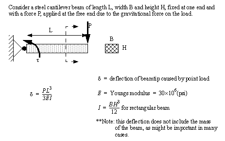
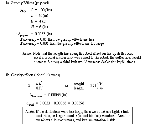
• Static considerations,
gravity effects cause downward deflection of the arm and support systems
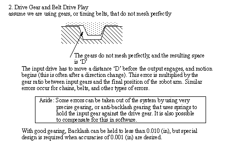
drive gears and belts often have noticeable amounts of slack (backlash) that cause positioning errors
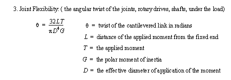
joint play (windup): when long rotary members are used in a drive system and twist under load
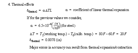
thermal effects: temperature changes lead to dimensional changes in the manipulator
• Dynamic considerations,
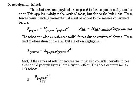
acceleration effects: inertial forces can lead to deflection in structural members. These are normally only problems when a robot is moving very fast, or when a continuous path following is essential. (But, of course, during the design of a robot these factors must be carefully examined)
• e.g.
35.2 Robot Types
35.2.1 Basic Robotic Systems
• The basic components of a robot are,
Structure: the mechanical structure (links, base, etc). This requires a great deal of mass to provide enough structural rigidity to ensure minimum accuracy under varied payloads.
Actuators: The motors, cylinders, etc. that drive the robot joints. This might also include mechanisms for a transmission, locking, etc.
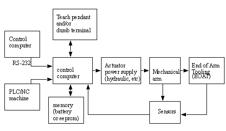
Control Computer: This computer interfaces with the user, and in turn controls the robot joints.
End of Arm Tooling (EOAT): The tooling is provided be the user, and is designed for specific tasks.
Teach pendant: One popular method for programming the robot. This is a small hand held device that can direct motion of the robot, record points in motion sequences, and begin replay of sequences. More advance pendants include more functionality.
35.2.2 Types of Robots
• Robots come in a wide variety of shapes, and configurations.
• The major classes of robots include,
arms: fixed in place, but can reach and manipulate parts and tools
mobile: these robots are free to move
35.2.2.1 - Robotic Arms
• Typical joint types are,
Revolute: rotary joints often driven by electric motors and chain/belt/gear transmissions, or by hydraulic cylinders and levers.
Prismatic: slider joints in which the link is supported on a linear slider bearing, and linearly actuated by ball screws and motors or cylinders.
• Basic configurations are,
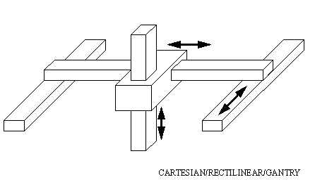
Cartesian/Rectilinear/Gantry: Positioning is done in the workspace with prismatic joints. This configuration is well used when a large workspace must be covered, or when consistent accuracy is expected from the robot.
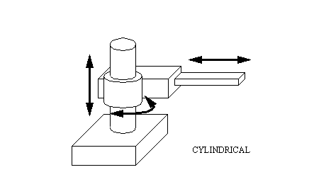
Cylindrical: The robot has a revolute motion about a base, a prismatic joint for height, and a prismatic joint for radius. This robot is well suited to round workspaces.
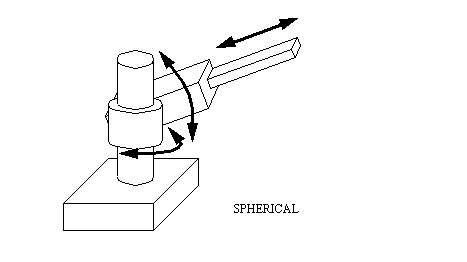
Spherical: Two revolute joints and one prismatic joint allow the robot to point in many directions, and then reach out some radial distance.
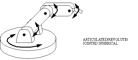
Articulated/Jointed Spherical/Revolute: The robot uses 3 revolute joints to position the robot. Generally the work volume is spherical. This robot most resembles the human arm, with a waist, shoulder, elbow, wrist.
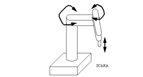
Scara (Selective Compliance Arm for Robotic Assembly): This robot conforms to cylindrical coordinates, but the radius and rotation is obtained by a two planar links with revolute joints.
35.2.2.2 - Autonomous/Mobile Robots
• The robots discussed up to this point have concerned ‘arms’ that are fixed to the floor. Another important class of robots are autonomous, and free to move about the workspace.
• Typical applications are,
nuclear accident cleanup
planetary exploration
Automatic Guided Vehicles in factories
mail delivery
35.2.2.2.1 - Automatic Guided Vehicles (AGVs)
• These are typically wheeled robots that carry payloads through a factory.
• They navigate using,
wires embedded in floors
light sources or reflectors
colored tapes on the floor
35.2.3 Commercial Robots
• Some specifications for commercial robots are given below
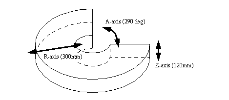
35.2.3.1 - Seiko RT 3000 Manipulator
• In general
Degrees of freedom 4
Maximum payload 5kg (11 lb)
Repeatability (based on constant temp., load, speed) +/-0.025mm (+/- 0.001 in.)
Weight 108kg (237 lb)
Operating Temperature 0C to 40C (32F to 104F)
Humidity (based on constant temp. load, speed) 20% to 90%
Power Requirements 200-240 VAC
Other 50-70 psig air
• A-axis
motion revolute
Range +/-145 degrees
Resolution 0.005 deg.
Speed
max. speed 150 deg/sec
max. torque 383. in.lbs
• Z-axis
motion linear
Range 4.72 in (120mm)
Resolution 0.0005 in (0.012mm)
Speed
max. speed 14 in/sec (360 mm/sec)
max. force 23.3-35.2 lbs (10.6-16.0 kg)
• R-axis
motion linear
Range 11.8 in (300mm)
Resolution 0.001 in (0.025mm)
Speed
max. speed 29.5 in/sec (750 mm/sec)
max. force 40 lbs
• T-axis
motion revolute
Range 290 degrees
Resolution 0.003 deg.
Speed
max. speed 90 deg/sec
max. torque 358. in.lbs
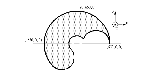
• The workspace is pictured below,
35.2.3.2 - DARL Programs
• All DARL comments follow ’ at any position on a line.
• Statements are ended with a colon, and as long as colons are used, more than one statement can be used on a line.
• Line numbering is required for DARL programs.
• Dimensions are given in millimeters in the programs.
• Commas and spaces are treated as equivalent.
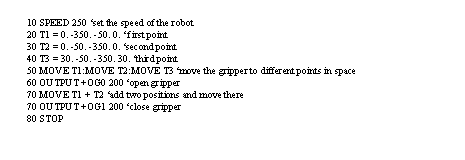
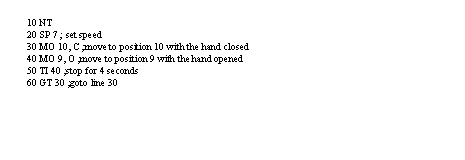
• A sample program is given below with comments for explanation,
35.2.3.2.1 - Language Examples
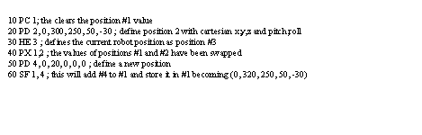
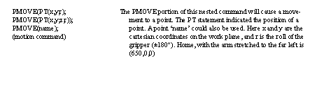
• First, points can be defined in programs, they can also be defined by moving the robot to the location and storing the value. This allows the robot to accurately find points without measuring. It also means that points location values don’t need to appear in programs, they are stored in memory.
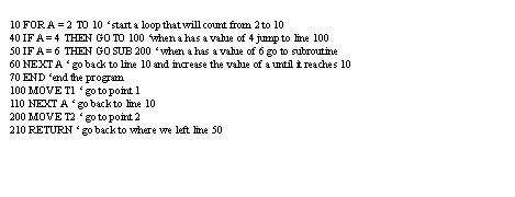
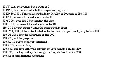
• A example that uses for-next, if-then, goto and gosub-return commands is shown below. These commands are very standard in their use.
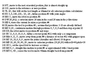
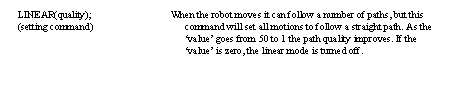
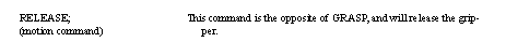
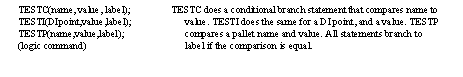
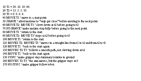
• A example that uses motion is shown below. The ‘move’ command causes a motion to another point by only turning the needed joints. ‘moves’ causes a more complex motion resulting in a straight line tool motion between points. ‘movec’ allows a circular interpolation dictated by three points (the start, and the two given). The shave command forces the robot to fully complete a motion and stop before going to the next point. The sync command will move the robot, but keep the gripper in the original position relative to the real world.
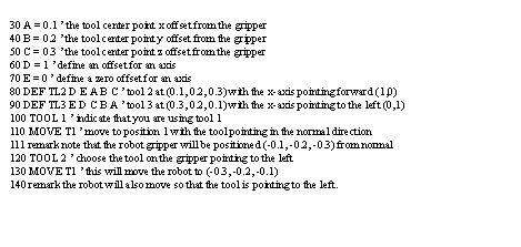
• A example that defines tool location offsets is shown below. This is particularly useful for a robot that has more than one tool attached. The normal tool location is on the end of the arm. With multiple tools attached we will have multiple tool center points. We can have a tool definition for each one of these. Note that the x-axis is the normal forward for the tool. The tool axis can only be changed in the x-y plane (or the plane perpendicular to the gripper rotation).
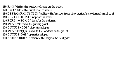
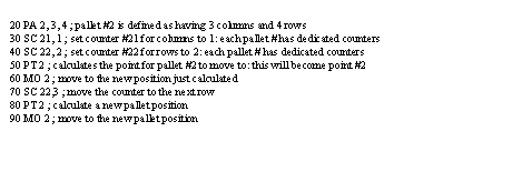
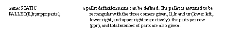
• A example that uses pallet commands is shown below. Basically a pallet allows us to create an array of points (it does the calculations). We can then give a location on a pallet and move to that point. The basic pallet definition requires that we indicate the number of rows and columns. We also need to define the physical locations of the rows and columns. We do this by giving an origin point, and then defining where the first row and column end. To use the pallet location we can simply refer to the pallet location index.
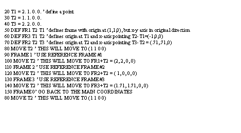
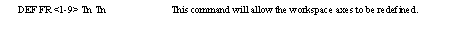
• A example that defines and uses new frames is shown below. We define a new frame of reference by using points. The first point becomes the new origin. The second point determines where the new x-axis points. The z-axis remains vertical, and the y-axis is shifted appropriately.
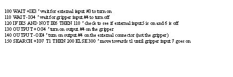
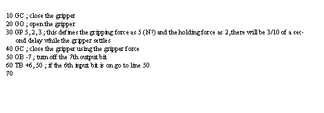
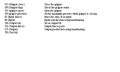
• A example that uses simple inputs and outputs is shown below. Note that there are two connectors for I/O. The main or ‘E’xternal connector is on the main controller box. The other I/O lines are on the ‘G’ripper. We can check the states of inputs and set the states of outputs. The ‘+’ sign indicates inputs/outputs high (5v) and the ‘-’ sign indicates low (0V). The ranges for input points are ie0-ie15, ig0-ig7, and for output points oe0-15, og0-7. The search command allows us to move the robot until an input is activated. This is useful when attempting to find a part by touching it.
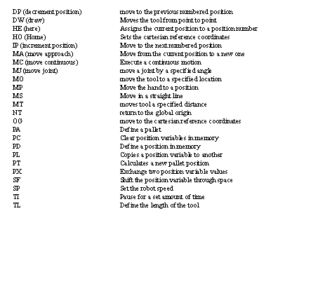
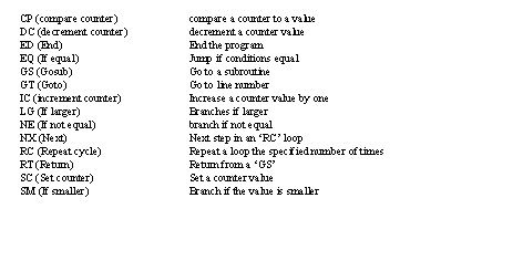
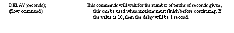
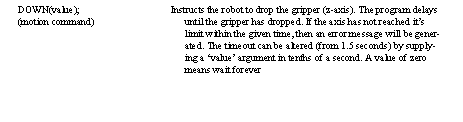
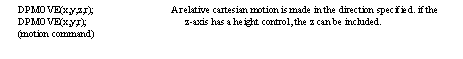
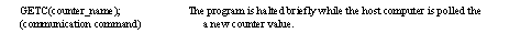
35.2.3.2.2 - Commands Summary
• A summary of the commands is given below,
35.2.3.3 - Mitsubishi RV-M1 Manipulator
• In general
Degrees of freedom 5
Maximum payload 1kg (2.2 lb)
Repeatability (based on constant temp., load, speed) +/- 0.3mm
Weight 19kg (42 lb)
Operating Temperature 5C to 40C
Humidity (based on constant temp. load, speed) 10% to 85%
Power Requirements 120/220/230/240 VAC
Other 50-70 psig air
• waist
motion revolute
Range 300 degrees
Resolution ?? deg.
Speed
max. speed 120 deg/sec
max. torque ?? in.lbs
• shoulder
motion revolute
Range 130 degrees
Resolution ?? deg.
Speed
max. speed 72 deg/sec
max. torque ?? in.lbs
• elbow
motion revolute
Range 110 degrees
Resolution ?? deg.
Speed
max. speed 109 deg/sec
max. torque ?? in.lbs
• wrist pitch
motion revolute
Range +/-90 degrees
Resolution ?? deg.
Speed
max. speed 100 deg/sec
max. torque ?? in.lbs
• wrist roll
motion revolute
Range +/-180 degrees
Resolution ?? deg.
Speed
max. speed 163 deg/sec
max. torque ?? in.lbs
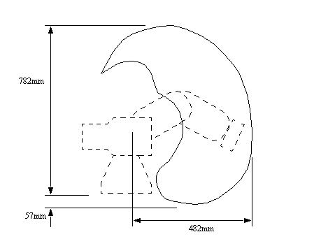
• The workspace is pictured below,
35.2.3.4 - Movemaster Programs
• All comments follow a semi-colon at any position on a line
• Statements are ended with a colon, and as long as colons are used, more than one statement can be used on a line.
• Line numbering is required.
• Dimensions are given in millimeters in the programs.
• A sample program is given below with comments for explanation,
35.2.3.4.1 - Language Examples
• The example below shows how points are defined and used. Please be aware that point location values are not normally defined in a program. Normally they are programmed by hand, and then when the program is run, it refers to them by number (from 1 to 629)
• The example below shows how we can define and use pallets. The definition of a pallet covers a number of lines to define the pallet size and then the location. We must also define points to indicate where the pallet lies in space. For the example below these points would have to be position numbers 20 (pallet origin), 21 (origin to end of first column), 22 (origin to end of first row), 23 (origin to diagonal corner of pallet). Note: if using pallet #3 these counters would be 30-33, and point 3 would move.
• The example below shows some of the position commands. These positions are normally defined outside the program by moving the robot to desired locations. These positions are not always absolute, and in some cases will act as displacement vectors.
• The example below shows some of the counter and branching functions. These tend to use a status register approach: for example, a value to be compared will be loaded on one line, the next line will compare it and a branch instruction will occur on the specified condition. For-next loops have been constructed as part of this example.
• The example below shows how to use various gripper and I/O functions. There are eight input bits and 8 output bits available.
35.2.3.4.2 - Command Summary
• A summary of the motion commands is given below,
• A summary of the program control commands is given below,
• A summary of the IO commands is given below,
35.2.3.5 - IBM 7535 Manipulator
• In general
Degrees of freedom 4
Maximum payload 6kg (13.2 lb)
Repeatability (based on constant temp., load, speed) +/-0.05mm (+/- 0.002 in.)
Weight 99kg (218 lb)
Operating Temperature 10C to 40.6C (50F to 106F)
Humidity (based on constant temp. load, speed) 8% to 80%
• Theta 1 axis
motion revolute
Range 0 to 200 degrees +/- 1deg.
Resolution 0.00459 deg.
Low speed (note: this is set by a switch)
max. speed 700 mm/sec (28 in./sec)
max. load 6 kg(13.2 lb)
Medium speed
max. speed 1100 mm/sec (43 in./sec)
max. load 6 kg(13.2 lb)
High speed
max. speed 1450 mm/sec (57 in./sec)
max. load 1 kg(2.2 lb)
• Theta 2 axis
motion revolute
Range 0 to 160 degrees +/- 1deg.
Resolution 0.009 deg.
Low speed (note: this is set by a switch)
max. speed 525 mm/sec (21 in./sec)
max. load 6 kg(13.2 lb)
Medium speed
max. speed 825 mm/sec (32 in./sec)
max. load 6 kg(13.2 lb)
High speed
max. speed 1000 mm/sec (39 in./sec)
max. load 1 kg(2.2 lb)
• Roll axis
motion revolute
Range +/- 180 degrees +/- 1.5 deg.
Holding Torque 35 kg-cm (30.4 in.-lb.)
Maximum load centered on Z-Axis 6 kg (13.2 lb)
Maximum speed 3.7 rad/sec (210 deg./sec. +/-5%)
Rotating Torque 14 kg-cm (12.2 in-lb)
Max. load inertia 0.1 kg-m**2 (0.074 slug-ft**2)
(Note: effects of off center loads not
considered, and lower maximum)
Resolution 0.36 deg.
• Z-Axis
motion prismatic
Range 75 mm (2.95 in.)
Maximum Payload 6.0 kg (13.2 lb)
Resolution Not Applicable
• Compressed Air
Maximum Pressure 6 kg/cm**2 (85 psig)
Conditioning Must be moisture free, as through a
moisture separator, and filtered with
regulator.
• The workspace is shown below,
35.2.3.6 - AML Programs
• All AML comments start with two dashes ‘--’ at any position on a line
• Statements are ended with a semi-colon, and as long as semi-colons are used, more than one statement can be used on a line.
• Line numbering is done by the AML Editor
• the free form variables/identifiers must: start with a letter; be up to 72 characters in length; use letters numbers and underscores, except in the last position.
• Statements have the general form,
• A sample program is given below with comments for explanation,
• A summary of the commands is given below,
• A summary of some of the keywords is,
35.2.3.7 - ASEA IRB-1000
• In general
maximum payload (for a 200mm tool offset) 6 kg
Maximum moment of inertia 2.5 Nm (dynamic)
Maximum static moment 12 Nm (static)
weight 125 kg
accuracy at wrist +/- 0.20mm
• Axis 1
joint type revolute
range 340 deg.
speed 95 deg/sec
actuator servo
• Axis 2
joint type revolute
range +/-40 deg.
speed 0.75 m/sec
actuator servo
• Axis 3
joint type revolute
range +/-25 deg. to -40 deg.
speed 1.1 m/s
actuator servo
• Axis 4
joint type revolute
range +/- 90 deg.
speed 115 deg/sec.
actuator servo
• Axis 5
joint type revolute
range +/- 180 deg.
speed 195 deg/sec
actuator servo
• Gripper
Pneumatic 2 solenoid valves are located in the
upper arm, and can be operated by
the programs.
electrical There is a four pole electrical outlet
in the upper arm for use with more
advanced grippers having search
functions.
35.2.4 Unimation Puma (360, 550, 560 Series)
• In general,
an articulated arm with 3 dof for positioning, and 3 dof for orientation
left/right arm configurations are possible
uses DC servo motors for drive
uses 110-130 VAC, 50-60Hz, 1.5KW
weight 120 lb
repeatability 0.004in
RS-232C port for dumb terminal
32 parallel I/O lines
memory 16K
programming language is VAL
• joint 1 (Waist)
joint type revolute
range 315°
max slew rate 1.9 rad/sec.
resolution .0001 rad/bit
maximum static torque 9.9Nm
• joint 2 (Shoulder)
joint type revolute
range 320°
max slew rate 1.8 rad/sec.
resolution .00009 rad/bit
maximum static torque 14.9Nm
• joint 3 (Elbow)
joint type revolute
range 300°
max slew rate 2.6 rad/sec.
resolution .000146 rad/bit
maximum static torque 9.1Nm
• joint 4 (Wrist Rotation)
joint type revolute
range 575°
max slew rate 8.7 rad/sec.
resolution .000181 rad/bit
maximum static torque 1.5Nm
• joint 5 (Wrist Bend)
joint type revolute
range 235°
max slew rate 5.6 rad/sec.
resolution .000199 rad/bit
maximum static torque 1.4Nm
• joint 6 (Flange Rotation)
joint type revolute
range 525°
max slew rate 5.2 rad/sec.
resolution .000247 rad/bit
maximum static torque 1.1Nm
35.3 Robot Applications
35.3.1 Overview
• Unlike many machines, robots are easy to imagine performing tasks, because of their similarity to the human form. This has caused many companies to adopt robots without properly assessing what their strengths and weaknesses are.
• The early days of experimentation lead to many failed applications, as well as some notable successes
• A useful dichotomy is,
Point-to-Point: A robot that typically only has 2 (or very few) possible positions. These are good for pick and place type operations, and they are often constructed with pneumatic cylinders.
Manipulation: A robot that assembles, or moves parts requires good end of path motion, but does not require as much accuracy in the middle of the path. A higher speed between path endpoints is often desired.
Path Tracking: When arc welding, gluing, etc. the robot must follow a path with high accuracy, and constant speed. This often results in slower motion, and more sophisticated control software.
Operating: The robot will be expected to apply forces to perform work at the end of the tool, such as doing press fits. While the demands for these robots is essentially the same, they must be capable of handling the higher forces required when in working contact with the work.
Telerobotics: Acts as a remote extension of human control, often for safety or miniaturization purposes. In these cases the robots often mimic the human form, and provide some forms of physical feedback.
Services: mail delivery, vacuuming, etc.
Biomedical: prosthetic and orthotic devices.
• The number of degrees of freedom of the robot should be matched to the tasks.
• Note: 5 d.o.f. robots will allow the tool to reach all points in space if the tool has an axis of symmetry. For example, a welding torch flame has a symmetrical axis.
• Some commercial applications that have been done with robots are,
die casting: used for unloading parts from dies, quenching parts, and trimming them with a trim press. The robot may also be used to put inserts into the die.
spot welding: spot welding electrodes are clamped in place, and the weld is made. The robot allows many welds to be done.
arc welding- continuous path robots are used to slowly track a path with a continuous rate, and with control of welding parameters.
investment casting: robots can be used in the pick and place operations involved in making the molds.
forging- a robot can be used to precisely position the work under the impact hammer, freeing a worker from the handling hot heavy work pieces.
press work- the robot handles loading parts into the press, and removing the resulting work pieces.
spray painting- a very popular application in which the robot sweeps the paint head across the surface to deposit a spray. This process has been coupled with electrostatics to improve efficiency and distribution.
plastic molding: they can be used for loading the hoppers, and unloading the parts. This is most effective when the parts are hard to handle.
foundry process- robots can be used for ladling materials, and preparation of molds.
machine tools- robots can be used for loading and unloading machine tools, and material transfer systems.
heat treatment process: parts can be loaded into the ovens, unloaded from the ovens, quenched and dried by robots.
metal deburring: continuous path robots can be used to track rough edges with a compliant tool design.
palletizing process: parts can be placed in boxes, or on skids in preparation for shipping. Most robots have program commands to support this.
brick manufacture: a robot can be used for loading and unloading a kiln, and stacking bricks for shipping.
glass manufacture: a robot can handle the breakable glass with a wide EOAT that prevents sagging, etc. The robot can also be used for grinding edges.
35.3.2 Spray Painting and Finishing
• Air spraying: air under pressure causes the paint to atomize and be propelled to the article to be painted
• Airless spraying: finishing materials, such as paint, are sprayed under considerable hydraulic pressure through a fixed orifice, which causes the paint to be atomized directly without the need for air.
• Electrostatic spraying: Atomized particles (paint or powder droplets) are electrostatically charged. These are attracted to the object being sprayed by the applied electrostatic field. Considerable material savings are achieved since very little of the sprayed material bypasses the object and is lost. Objects being sprayed are kept at a ground potential to achieve a large electrostatic field.
• Heating of materials: paint decreases in viscosity when heated and can be sprayed with lower pressures. Less solvent is required and there is less overspray of paint. Heating may be used with any of the preceding systems
• Air spraying and electrostatic spraying are the most common methods of application for paints, enamels, powders, and sound absorbing coatings.
35.3.3 Welding
• These tasks are characterized by the need for,
smooth motion
conformity to specified paths
consistent tool speed
35.3.4 Assembly
• General concepts are,
one or more robots
each robot may perform a variety of sub-assemblies
requires a conveyor and inspection station
A host computer must synchronize robot actions
A bad part rejection function should be available
An organized output should be used, e.g. pallets, or shipping crates.
• These tasks are common, but face stiff competition from fixed automation and manual labor.
35.3.5 Belt Based Material Transfer
• When a robot is used in a workcell, the raw part is delivered in, worked on, and then moved out. This can be done using moving belts, etc.
• Parts are placed directly on the belt, or placed on pallets first.
• Belts can travel in straight paths, or in curved paths if flexible belt link designs are used.
• If straight belts are used, transfer points can be used at the end to change part/pallet direction
• When pallets are used, there is a fixture on top designed to hold the part in an accurate position so that robots and other equipment will be able to locate the part within some tolerance.
• Vision systems may be necessary if part orientation cannot be fixed.
35.4 End Of Arm Tooling - EOAT
• The best known universal gripper: the human hand
• Useful classifications are,
Grippers
multiple/single
internal/external
Tools
compliant
contact
non-contact
• End of arm tooling is typically purchased separately, or custom built.
35.4.1 EOAT Design
• Typical factors to be considered are,
Workpiece to be handled
part dimensions
mass
pre- and post- processing geometry
geometrical tolerances
potential for part damage
Actuators
mechanical
vacuum
magnet
etc.
Power source of EOAT
electrical
pneumatic
hydraulic
mechanical
Range of gripping force
object mass
friction or nested grip
coefficient of friction between gripper and part
maximum accelerations during motion
Positioning
gripper length
robot accuracy and repeatability
part tolerances
Maintenance
number of cycles required
use of separate wear components
design for maintainability
Environment
temperature
humidity
dirt, corrosives, etc.
Temperature protection
heat shields
longer fingers
separate cooling system
heat resistant materials
Materials
strong, rigid, durable
fatigue strength
cost and ease of fabrication
coefficient of friction
suitable for environment
Other points
interchangeable fingers
design standards
use of mounting plate on robot
gripper flexible enough to accommodate product design change
• The typical design criteria are,
low weight to allow larger payload, increase accelerations, decrease cycle time
minimum dimensions set by size of workpiece, and work area clearances
widest range of parts accommodated using inserts, and adjustable motions
rigidity to maintain robot accuracy and reduce vibrations
maximum force applied for safety, and to prevent damage to the work
power source should be readily available from the robot, or nearby
maintenance should be easy and fast
safety dictates that the work shouldn’t drop when the power fails
• Other advanced design points,
ensure that part centroid is centered close to the robot to reduce inertial effects. Worst case make sure that it is between the points of contact.
holding pressures/forces/etc are hard to control, try to hold parts with features or shapes
compliance can help guide work into out-of-alignment conditions.
sensors in the EOAT can check for parts not in the gripper, etc.
the gripper should tolerate variance in work position with part alignment features
gripper changers can be used to make a robot multifunctional
multiple EOAT heads allow one robot to perform many different tasks without an EOAT change.
*** Don’t try to mimic human behavior.
design for quick removal or interchange of tooling by requiring a small number of tools (wrenches, screwdrivers, etc).
provide dowels, slots, and other features to lead to fast alignment when changing grippers.
use the same fasteners when possible.
eliminate sharp corners/edges to reduce wear on hoses, wires, etc.
allow enough slack and flexibility in cables for full range of motion.
use lightweight materials, and drill out frames when possible.
use hard coatings, or hardened inserts to protect soft gripper materials.
examine alternatives when designing EOAT.
the EOAT should be recognized as a potential bottleneck, and given extra design effort.
use shear pins, and other devices to protect the more expensive components.
consider dirt, and use sealed bearings where possible.
move as much weight away from the tip of the gripper towards the robot.
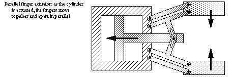
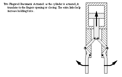
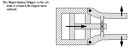
35.4.2 Gripper Mechanisms
• A gripper is specifically EOAT that uses a mechanical mechanism and actuator to grasp a part with gripping surfaces (aka fingers)
• Quite often gripper mechanisms can be purchases, and customized fingers attached.
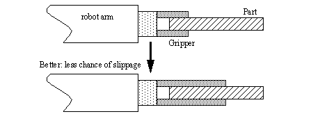
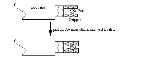
• Fingers are designed to,
1. Physically mate with the part for a good grip
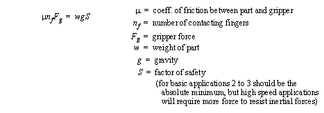
2. Apply enough force to the part to prevent slipping
• Movements of the fingers
pivoting (often uses pivotal linkages)
linear or translational movement (often uses linear bearings and actuators)
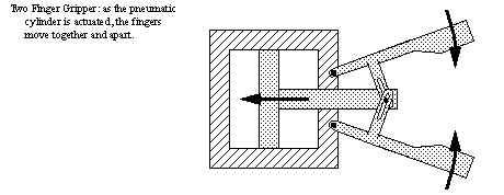
• Typical mechanisms
linkage actuation
gear and rack
cam
screw
rope and pulley
miscellaneous: eg. bladder, diaphragm
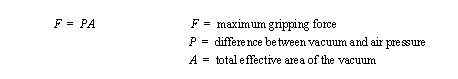
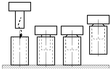
35.4.2.1 - Vacuum grippers
• Suction cups can be used to grip large flat surfaces. The cups are,
typically made of soft rubber or plastic
typically round, or oval shapes
• A piston operated vacuum pump (can give a high vacuum), or a venturi valve (simpler) can be used to generate the vacuum.
• The surfaces should be large, smooth, clean.
• The force of a suction cup depends on the effective area of the vacuum and the difference in the vacuum, and air pressures.
• e.g.
• Advantages,
requires only one surface of a part to grasp
a uniform pressure can be distributed over some area, instead of concentrated on a point
the gripper is light weight
many different types of materials can be used
• Disadvantages,
the maximum force is limited by the size of the suction cups
positioning may be somewhat inaccurate
time may be needed for the vacuum in the cup to build up
35.4.3 Magnetic Grippers
• Can be used with ferrous materials
• Electromagnets,
easy to control, requires a power supply, and a controller
polarity can be reversed on the magnet when it is put down to reverse residual magnetism
• Permanent magnets,
external power is not required
a mechanism is required to separate parts from the magnet when releasing
good for environments that are sensitive to sparks
• Advantages,
variation in part size can be tolerated
ability to handle metal parts with holes
pickup times fast
requires only one surface for gripping
can pick up the top sheet from a stack
• Disadvantages,
residual magnetism that remains in the workpiece
possible side slippage
35.4.3.1 - Adhesive Grippers
• Can handle fabrics and other lightweight materials
• These grippers are basically a sticky surface on the end of the robot
• As the adhesive gripper is repeatedly used, it loses stickiness, but a tape roll can be used to refresh the sticky surface.
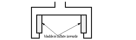
35.4.4 Expanding Grippers
• Some parts have hollow cavities that can be used to advantage when grasping.
• A bladder can be inserted into a part, and then inflated. This forms a friction seal between the two, and allows manipulation. When done the pressure is released, and the part freed.
• Expanding grippers can also be used when gripping externally.
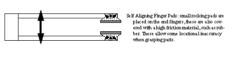
35.4.5 Other Types Of Grippers
• Most grippers for manipulation are sold with mounts so that fingers may be removed, and replaced.
• Gripper fingers can be designed to reduce problems when grasping.
35.5 Advance Topics
35.5.1 Simulation/Off-line Programming
• How a robot interacts with the environment makes it difficult to program off-line. To do this successfully, a complete simulation of the robot workspace is required.
• One excellent example of a simulation package is CIMStation by Silma. It allows full construction of the robots workspace, and subsequent testing.
• Examples of simulated operation in CIMStation are,
painting
NC code verification
tool and fixture simulation
Design For Manufacturing
process planning
composite tape layup
composite filament layup
spot welding
arc welding
material/work manipulation
collision detection
deburring
inspection
kinematic and dynamic simulation
controller simulation
• The simulators available for the robots in the lab allow off-line programming and simulations.
35.6 Problems
Problem 35.1 a) What are some basic functions expected on a robot teach pendant
b) Describe how a computer can help avoid debug robot programs without a robot being used
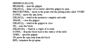
Problem 35.2 Write a short program to direct a robot to pick up and put down a block. Assume the points have already been programmed with the teach pendants.
a) Write program for the IBM 7535.
b) Write program for the Seiko RT-3000.
c) Write program for the Mitsubishi RV-M1.
Answer 35.2
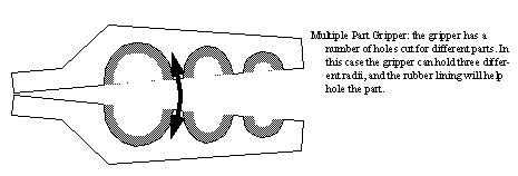
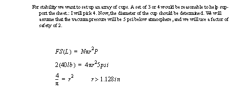
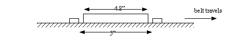
Problem 35.3 We plan to use a pneumatic gripper to pick up a 4 by 8 sheet of glass weighing 40 lbs. Suggest a gripper layout and dimensions of the cups. State any assumptions.
Answer 35.3
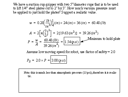
Problem 35.4 A vacuum pump to be used in a robot vacuum gripper application is capable of drawing a negative pressure of 4.0 psi compared to atmospheric. The gripper is to be used for lifting stainless steel plates, each plate having dimensions of 15” by 35”, and weighing 52 lbs. Determine the diameter of the suction cups to be used for the gripper if it is decided to use two cups for greater stability. A factor of safety of 1.5 should be used in the computations.
Consider the following gripper design problems.
a) We plan to use a friction gripper to pick up a 50 lb iron plate. Suggest a gripper design and specify the force required.
b) Design an end effector, and describe the path planning approach for a robot unloading satellites from the space shuttle.
Problem 35.5 What is the workspace for each of the robots below, and can the robots reach all positions and orientations in the workspace?
Problem 35.6 Suggest a type of robot suitable for the following tasks. Briefly explain your suggestion.
a) placing pallets on rack shelving
b) electronics assembly
c) loading and unloading parts from an NC mill
Answer 35.6 a) cartesian: well suited to cartesian layout of shelves.
b) scara: will work on a flat table well.
c) articulated: can easily move around obstructions.
Problem 35.7 Suggest a type of robot suitable for the following tasks. Briefly explain your suggestion.
a) a gas pump robot for placing the gas nozzle into the fuel tank.
b) for drilling holes in a printed circuit board.
c) to vacuum a hotel.
Problem 35.8 Why are 5 axis enough for some robotic applications (eg. welding) and all NC milling operations?
Problem 35.9 You have been asked to write a program for a robot (you can choose either the Seiko RT-3000 or Mitsubishi RV-M1). The program is to pick up a part at point T1, move to point T2, and then load the part into a pallet. The robot should then return to point A to pick up then next part. This should continue until the pallet is full.
T1 = (300, 300, 20)
T2 = (-300, 300, 0)
Pallet has 6 rows and 7 columns
Pallet origin T3 = (300, 0, 0)
Pallet end of row T4 = (350, 0, 0)
Pallet end of column T5 = (300, 60, 0)
Answer 35.9
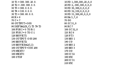
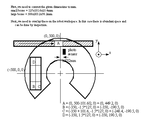
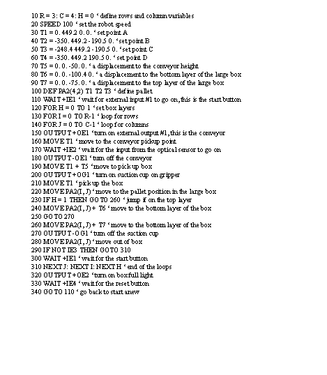
Problem 35.10 An IBM 7535 industrial robot is to be used to unload small 1 lb. cardboard boxes (5” by 4” by 1”) from a conveyor, and stack them in a large cardboard box (20” by 8” and 2” deep). After the large box is loaded, it will be removed automatically and replaced with an empty one. The conveyor will be controlled by a robot output, and it will be stopped when an optical sensor detects a small box. When the box is full the conveyor will be stopped and a light turned on until an unload button is pushed. The entire system uses a start and stop button combination. The stop button is not an e-stop, but it will stop the cycle after the small box is placed in the large box.
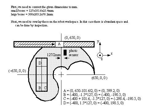
a) Layout the position of the conveyor, sensor, large box and robot so that all positions can be reached. Indicate critical points of objects.
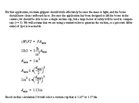
b) Design a robot gripper to pick up the boxes.
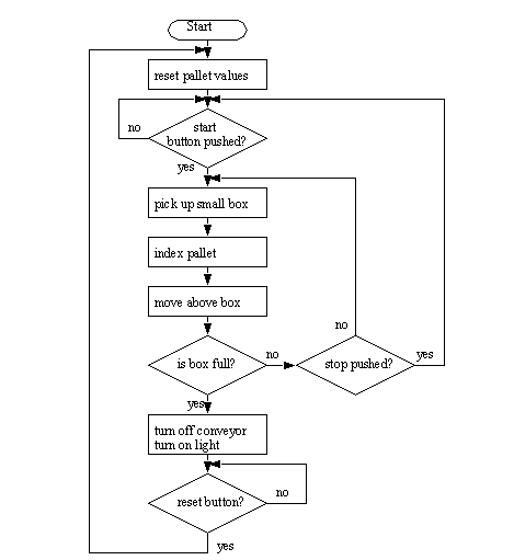
c) Develop a flow chart for the robot operations.
d) Write an AML program for the flowchart.
Answer 35.10 a)
b)
c)
Problem 35.11 Repeat the previous problem for the Seiko RT-3000 robot.
Answer 35.11 a)
b)
c)
d)
Problem 35.12 Given the scenario below, find the minimum angular resolution of the rotating sensor.
- the robot has +/- 0.5” accuracy
- the pallet can slide +/- 0.1” on the belt
- the driving motor is continuous, and can be run to any angle
- the rotating sensor is an incremental encoder, every rotation of some small angle it issues a pulse. But, because of the construction of the device, it has a minimum resolution for angular measurements
- the robot must be able to touch the part to pick it up
- the tool on the end of the robot is a 1” magnet, and it must be able to touch the part completely to pick it up.
- pulley size is 10” dia.
Problem 35.13 The IBM 7535 robot arm moves its TCP to point (-450, 250)mm at speeds programmed by ‘payload(5)’ and decelerates from the resultant speed to zero in 0.5 seconds. The tool has a mass of 1.5 kg with its center of gravity at 3cm from the TCP and transfers a mass of 4kg with its C.G. at 5cm from the TCP.
a) determine the inertia torque about the theta1 axis showing all correct units
b) compare the value in a) with a maximum inertia torque estimated from decelerating a 6kg mass from 1100mm/s to zero in 0.5 sec.
c) Estimate the combined error at the CG of the load due to theta1 and theta 2 resolution
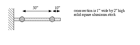
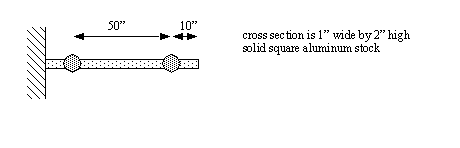
Problem 35.14 Consider a double jointed manipulator as shown below. It is subjected to a loading at the tip of 8 lbs, and works in a heated environment (i.e. T0(room temp.) = 60°F and T1 (working temp.) = 80°F.
a) Determine the elongation of the manipulator.
b) Determine the total linear deflection of the manipulator.
c) Determine the total final accuracy of the manipulator of the tip of the manipulator.
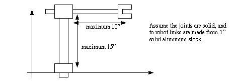
Problem 35.15 For the robot pictured below, assume the that a maximum payload of 10kg is specified. The joints are controlled by stepper motors with 200 steps per revolution. Each of the joints slides, and the gearing is such that 1 revolution of the stepper motor will result in 1” of travel. What is the accuracy of the robot?
Problem 35.16 Consider a double jointed manipulator as shown below. It is subjected to a loading at the tip of 8 lbs, and works in a heated environment (i.e. T0(room temp.) = 60°F and T1 (working temp.) = 80°F.
a) Determine the elongation of the manipulator.
b) Determine the total linear deflection of the manipulator.
c) Determine the total final accuracy of the manipulator of the tip of the manipulator.