
• PLC’s are generally used to control the supply of power to a system. As a result, a brief examination of electrical supply wiring diagrams is worthwhile.
• Generally electrical diagrams contain very basic circuit elements, such as relays, transformers, motors, fuses, lights, etc.
• Within these systems there is often a mix of AC and DC power, but 3 phase AC power is what is delivered universally by electric utilities, so the wiring diagrams focus on AC circuits.
• A relay diagram for a simple motor with a seal in circuit might look like the one shown below,

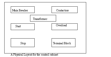
• The circuit designed for the motor controller must be laid out so that it may be installed in an insulated cabinet. In the figure below, each box could be a purchased module(s).
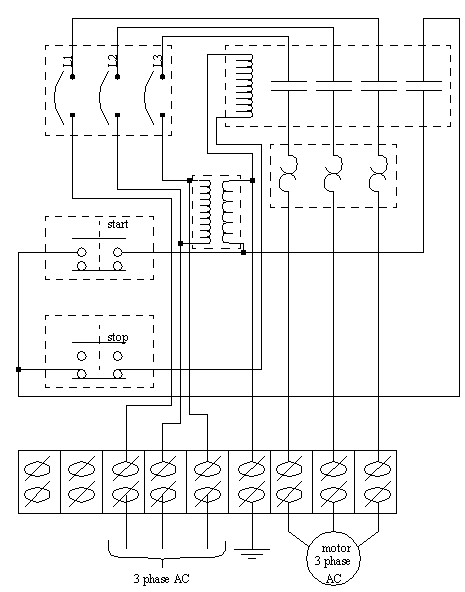
• After the Layout for the cabinet is determined, the wire paths must be determined. The figure below lays out the wire paths, and modules to be used.
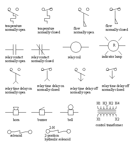
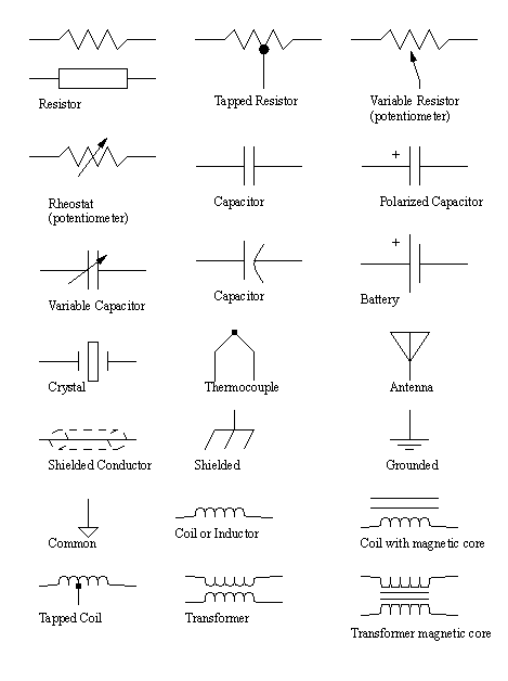
• The last section contained an example of an electrical control system for a motor. It used a number of symbols to represent elements.
• The Joint International Committee (JIC) developed a standard set of symbols for representing electrical circuit elements. These are given below.



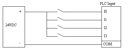
• Discrete inputs: If a group of input voltages are the same, they can be grouped together. An example of this is shown below.
• If the input voltages are different and/or come from different sources, the user might use isolated inputs.
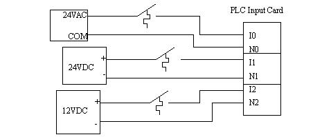
• There are two problems that occur in these systems,
1. Different power sources in the same system can cause different power supply voltages at opposite ends of a wire. As a result a current will flow, and an unwanted voltage appears. This can destroy components and create false signal levels.
2. Magnetic fields crossing the long conductors or in conductor loops can induce currents, and destroy equipment, give false readings, or add unwanted noise to analog data signals.
• Typical sources of grounding and shielding problems are,
• General shielding design points,
choose a metal cabinet that will shield the control electronics
avoid “noisy” equipment when possible
separate voltage levels, and AC/DC wires from each other when possible.
use shielded cables and twisted pair wires
Resistance coupled devices can have interference through a common power source, such as power spikes or brownouts caused by other devices in a factory.
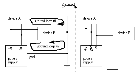
Ground loops are caused when too many separate connections to ground are made creating loops of wire that become excellent receivers for magnetic interference that induces differences in voltage between grounds on different machines. The common solution is to use a common ground bar.
The case of an object should be tied to ground to give current a path to follow in the case of a fault that energizes the case. (Note: fuses or breakers will cut off the power, but the fault will be on for long enough to be fatal.)
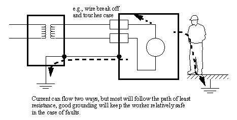
• Good grounding rules include,
each PLC component should be grounded back to the main PLC chassis
the ground wire should be separated from power wiring in enclosures
use star washers to ensure good electrical connection
mount ground wires on bare metal, remove paint if needed
use 12AWG stranded copper for PLC equipment grounds and 8AWG stranded copper for enclosure backplate grounds
connect the enclosure to the ground bus
connect the machine ground to the enclosure ground
the ground connection should have little resistance (<0.1 homs is good)
• Electrocution potential must be observed.
Safe current levels are listed below. But be aware that in certain circumstances very low currents can kill, when in doubt, take no chances.

Step potential is another problem. Electron waves from a fault travel out in a radial direction through the ground. If a worker has two feet on the ground at different radial distances, there will be a potential difference between the feet that will cause a current to flow through the legs. The gist of this is: if there is a fault, don’t run/walk away/towards.
Always ground systems first before applying power. (The first time a system is activated it will have a higher chance of failure.)
• Fail-safe wiring should be used so that if wires are cut or connections fail, the equipment should turn off. e.g., if a normally closed stop button is used, and the connector is broken off, it will cause the machine to stop, as if the stop button has been pressed, and brake the connection.
NO (Normally open): When wiring switches or sensors that start actions, use normally open switches so that if there is a problem the process will not start.
NC (Normally Closed): When wiring switches that stop processes use normally closed so that if they fail the process will stop. E-Stops must always be NC, and they must cut off the master power, not just be another input to the PLC.
always use a master power relay that will shut down the process, and connect it to the E-stop system.
use electrical wiring to handle all safety functions
shutdown buttons must be easily accessible from all points around the machine
• Some of the basic rules are,
a fail-safe design: Programs should be designed so that they check for problems, and shut down in safe ways. Most PLC’s also have imminent power failure sensors, use these whenever danger is present to shut down the system safely.
proper programming techniques and modular programming will help detect possible problems on paper instead of in operation.
make the program inaccessible to unauthorized persons
use predictable, non-configured programs
directly connect emergency stops to the PLC, or the main power supply
check for system OK at start-up
provide training for new users and engineers to reduce careless and uninformed mistakes
use PLC built in functions for error and failure detection
use well controlled startup procedures that check for problems
provide clear and current documentation for maintenance and operators
modular well designed programs
• A reasonable troubleshooting guide (note: not debugging),
1. Look at the process and see if it is in a normal state. i.e. no jammed actuators, broken parts, etc. If there are visible problems, fix them and restart the process.
2. Look at the PLC to see which error lights are on. Each PLC vendor will provide documents that indicate which problems correspond to the error lights. Common error lights are given below. If any off the warning lights are on, look for electrical supply problems to the PLC.
HALT: something has stopped the CPU
RUN: the PLC thinks it is OK (and probably is)
ERROR: a physical problem has occurred with the PLC
3. Check indicator lights on I/O cards, see if they match the system. i.e., look at sensors that are on/off, and actuators on/off, check to see that the lights on the PLC I/O cards agree. If any of the light disagree with the physical reality, then interface electronics/mechanics need inspection.
4. Consult the manuals, or use software if available. If no obvious problems exist the problem is not simple, and requires a technically skilled approach.
5. If all else fails call the vendor (or the contractor) for help.
• But if you really have to, remember that the machine can be unsafe while doing this.
• While a program is running in a PLC, you can specifically force inputs or outputs to turn on/off. This is best use for,
testing outputs: if you are doing this you will be checking wiring and the output card. This can be done directly.
force inputs to determine how the program will respond: if you are doing this you don’t understand your program, and you should sit down and figure it out.
• Possible bad outcome of forcing outputs,
damaged or jammed machine components
• Care must be taken to avoid certain environmental factors.
Dirt: Dust and grime can enter the PLC through air ventilation ducts. As dirt clogs internal circuitry, and external circuitry, it can effect operation. A storage cabinet such as Nema 4 or 12 can help protect the PLC.
Humidity: Humidity is not a problem with many modern materials. But, if the humidity condenses, the water can cause corrosion, conduct current, etc. Condensation should be avoided at all costs.
Temperature: The semiconductor chips in the PLC have operating ranges where they are operational. As the temperature is moved out of this range, they will not operate properly, and the PLC will shut down. Ambient heat generated in the PLC will help keep the PLC operational at lower temperatures (generally to 0°C). The upper range for the devices is about 60°C, which is generally sufficient for sealed cabinets, but warm temperatures, or other heat sources (e.g. direct irradiation from the sun) can raise the temperature above acceptable limits. In extreme conditions heating, or cooling units may be required. (This includes “cold-starts” for PLCs before their semiconductors heat up).
Shock and Vibration: The nature of most industrial equipment is to apply energy to change workpieces. As this energy is applied, shocks and vibrations are often produced. Both will travel through solid materials with ease. While PLCs are designed to withstand a great deal of shock and vibration, special elastomer/spring or other mounting equipment may be required. Also note that careful consideration of vibration is also required when wiring.
Interference: Electromagnetic fields from other sources can induce currents.
Power: Power will fluctuate in the factory as large equipment is turned on and off. To avoid this, various options are available. Use an isolation transformer. A UPS (Uninterruptable Power Supply) is also becoming an inexpensive option, and are widely available for personal computers.
• NEMA has provided a set of ratings for cabinets housing voltages less than 1000V AC. The basic classifications are outlined below,
Type 1: General purpose: indoors
Type 2: Dirt and water resistant: indoors
Type 3: Dust-tight, rain-tight and sleet(ice) resistant: outdoors
Type 3R- Rainproof and sleet(ice) resistant: outdoors
Type 3S- Rainproof and sleet(ice) resistant: outdoors
Type 4: Water-tight and dust-tight: indoors and outdoors
Type 4X: Water-tight and Dust-tight: indoors and outdoors
Type 5: Dust-tight and dirt resistant: indoors
Type 6: Waterproof: indoors and outdoors
Type 6P: Waterproof submersible: indoors and outdoors
Type 7: Hazardous locations: class I
Type 8: Hazardous locations: class I
Type 9: Hazardous locations: class II
Type 10: Hazardous locations: class II
Type 11: Gas-tight, water-tight, oiltight: indoors
Type 12: Dust-tight and drip-tight: indoors
Type 13: Oil-tight and dust-tight: indoors
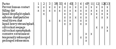
• Most factory floor applications are well suited to type 12 enclosures.
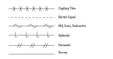
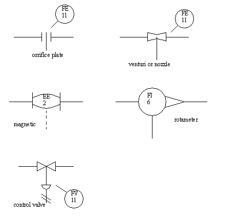
• Sensor and actuator symbols include,
31.1 Paques, Joseph-Jean, “Basic Safety Rules for Using Programmable Controllers”, ISA Transactions, Vol. 29, No. 2, 1990.
Problem 31.1 The best location for the PLC enclosure is:
a) close to the incoming power
c) close to the machine or process
d) far away from the machine or process
Problem 31.2 Typically, programmable controller systems installed inside an enclosure can withstand a maximum of:
Problem 31.4 The I/O placement and wiring documents should be updated:
Problem 31.6 Draw the electrical schematic and panel layout for the relay logic below. The system will be connected to 3 phase power. Be sure to include a master power disconnect.
