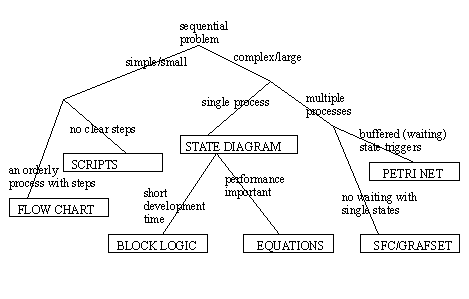
20. Sequential Logic Design
• This is for systems that move between different ‘modes’ of operation.
• These techniques allow different levels of design sophistication.
• In general the techniques and tools can be selected as shown below.
20.1 Scripts
• Another method that can be used to explore a state based program is a script. Another way to describe this is “what is happening, what started it and what will stop it?”
• The general hierarchy for a script is below,
• After we get a process description it must be rewritten as a script. Care is needed to check for consistency.
• This can be put into ladder logic. (clearly this logic is not complete and extra work is needed make it ready for the PLC)
• Implemented for an Allen Bradley PLC it might look like.
• General rules for scripting are,
1. At least one sentence is needed for at least each output.
2. The list of conditions should refer to other conditions.
3. The script should refer to actual inputs/outputs, memory locations or state names.
• This method is not rigorous and can be inadequate for many designs.
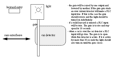
• Use the method to design a parking gate controller.
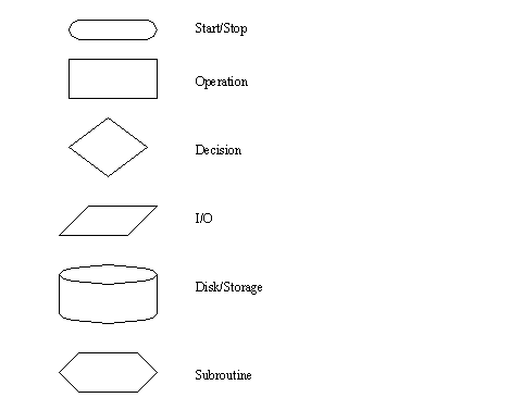
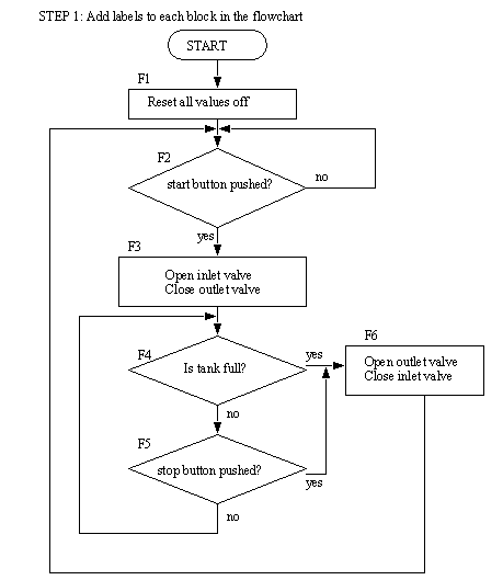
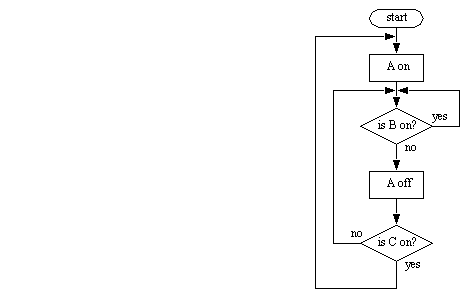
20.2 Flow Charts
• Good when the PLC only does one thing at a time in a predictable sequence.
• Basically, we can follow a flowchart one step at a time. Connecting lines indicate the sequences, and the shapes indicate the action/function.
• The real advantage is in modeling the process in an orderly manner.
• General rules for putting these together are,
determine what the major actions are, these become the boxes.
determine what sequence the actions normally follow, this determines the lines between elements.
determine where the sequence may change, these become the decision diamonds.
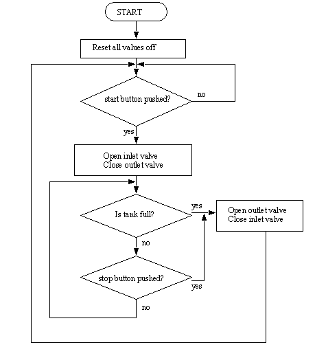
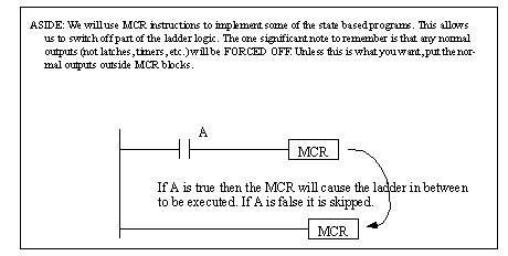
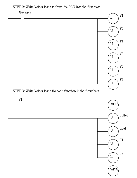
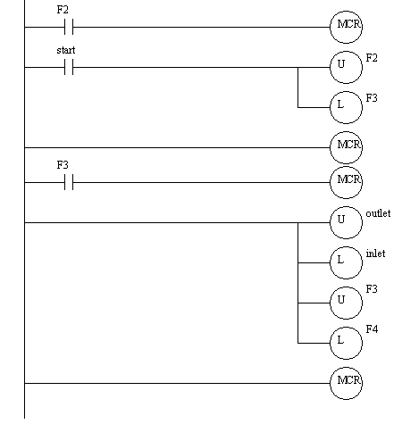
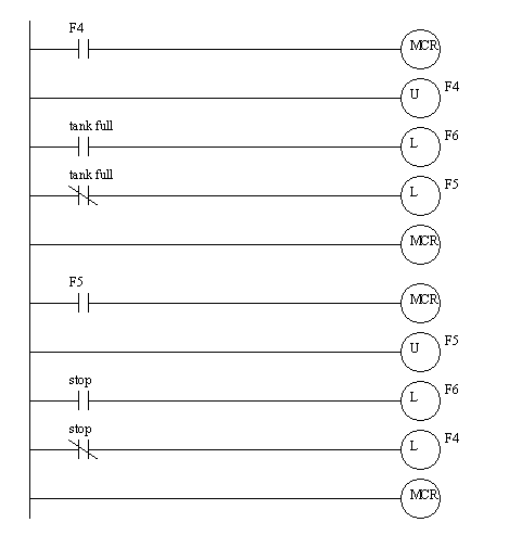
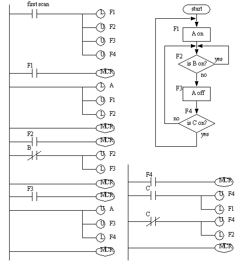
• The flowchart from the previous example can be converted to ladder logic. The first step is to name each state. From there the states can be converted to ladder logic using MCR blocks.
Problem 20.1 Draw a flow chart for cutting the grass, then develop ladder logic for three of the actions/decisions.
20.3 State Based Modeling
• When we have a single sequence of modes we can use state diagrams.
• State diagrams divide a system behavior into discrete states.
• The basic technique uses states and transitions to model the systems.
• The most essential part of creating state diagrams is identifying states. Some key questions to ask are,
1. Consider the system,
What does the system do normally?
Does the system behavior change?
Can something change how the system behaves?
Is there a sequence to actions?
2. List ‘modes’ of operation where the system is doing one identifiable activity that will start and stop. Keep in mind that some activities may just be to wait.
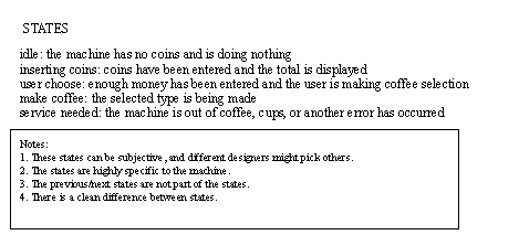
• Consider a coffee vending machine,
• These states can be organized into a state diagram and transitions can be added.
Problem 20.2 Draw a state diagram for A hydraulic press that will advance when two palm buttons are pushed. Top and bottom limit switches are used to reverse the advance and stop after a retract. At any time the hands removed from the palm button will stop an advance and retract the press.
Problem 20.3 Draw a state diagram for a microwave oven.
20.3.1 State Diagrams Example
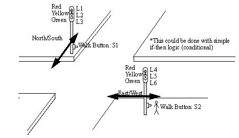
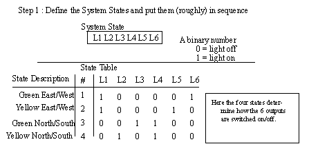
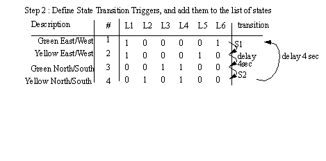
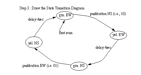
• A Complex Example: In this case we have a set of traffic lights. The lights will remain green in one direction until a pedestrian cross button is pushed. They will then turn yellow for four seconds and then turn red.
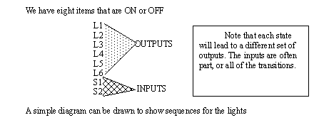
• First we will describe the system variables. These will vary as the system moves from state to state. Please note that some of these together can define a state (alone they are not the states).
• We can then use outputs, or controlled variables, to indicate system states (you can also think of these as modes).
• State transitions are determined based on inputs, and how the system changes. These events cause a change between states. Care must be taken to avoid confusing them with states.
• The state transition diagram allows us to visually check for continuous loops. In a simple state diagram multiple transitions may lead to alternate paths.
Problem 20.4 For the previous traffic light example, add a speed up signal for an emergency vehicle. A strobe light mounted on fire trucks will cause the lights to change so that the truck doesn’t need to stop. Modify the state diagram to include this option.
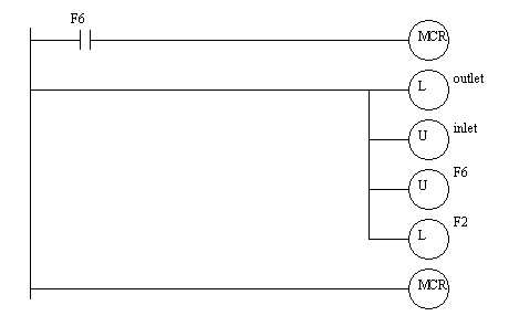
20.3.1.1 - Block Logic Conversion
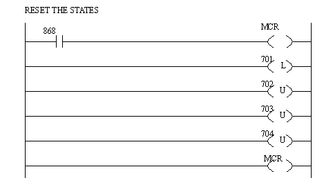
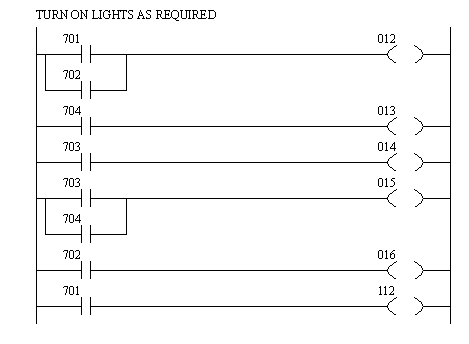
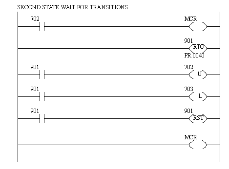
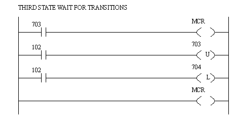
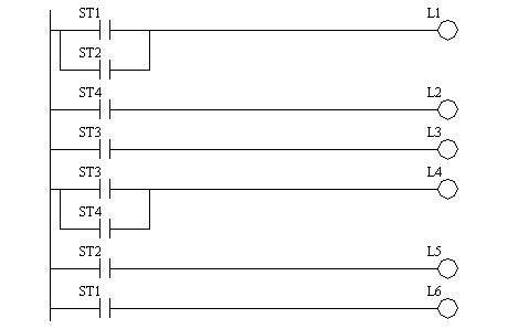
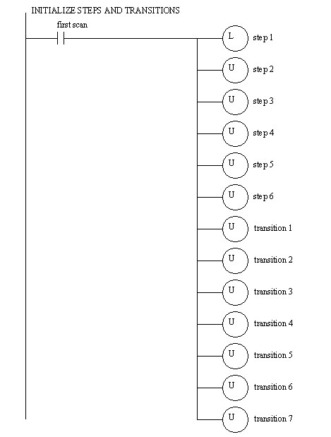
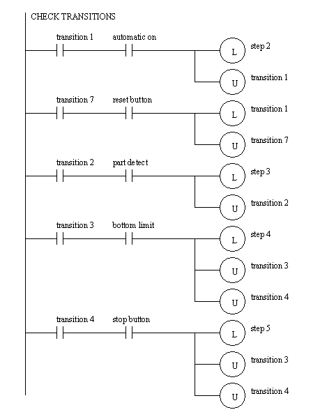
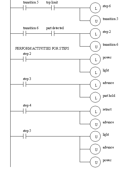
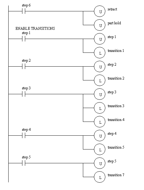
• The state diagram can be implemented in ladder logic, in this case for a SLC-150. This example uses states to turn lights on or off. An initial block uses the first scan input ‘868’ to ensure the first state is state 1. Each state runs a section of ladder logic code in ‘MCR’ blocks to wait for transitions.
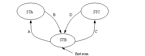
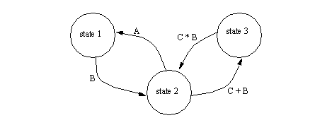
• Consider the state diagram below and implement it in ladder logic. You should anticipate what will happen if both A and C are pushed at the same time.
Problem 20.5 For the previous traffic light example, add a speed up signal for an emergency vehicle. A strobe light mounted on fire trucks will cause the lights to change so that the truck doesn’t need to stop. Create the ladder logic for the state diagram created previously.
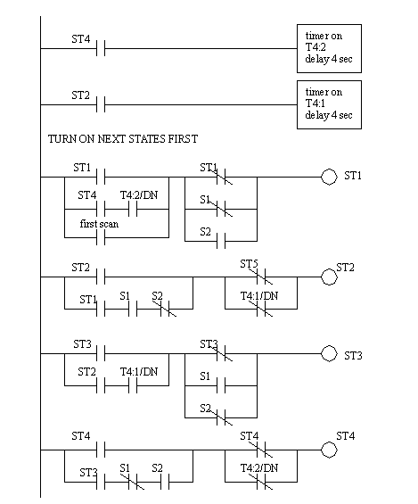
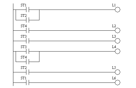
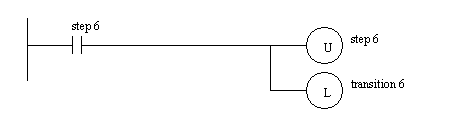
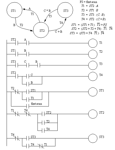
20.3.1.2 - Single State Equations
• This is the most compact method, but it comes at the cost of robustness.
• We can also model state diagrams with equations. To do this we can continue the traffic light example from before.
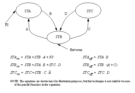
• This method will provide the most compact code, but there are two potential problems. Consider the example above.
1. In one scan ST2 might turn on, but ST1 is calculated above it in the ladder logic, so it would not turn off until the next scan: states ST1 and ST2 would both be on for one scan.
2. If in the second scan the input that caused the transition S1 turns off (it is an input on for a brief time) then ST1 would not turn off, and both ST1 and ST2 would be on indefinitely.
3. It is also possible for states that have multiple transitions to go to multiple states.
• The problem of dual states will occur for at least one of the transitions in this system, and must be tolerable in any system.
• The problem of inputs that are only one cycle long can be solved with a seal in or latch circuit.
• The problem of parallel state branches can occur if transitions are defined to be mutually independent. This can be overcome by adding terms to the transition logic that will suppress a transition when the competing transition is active.
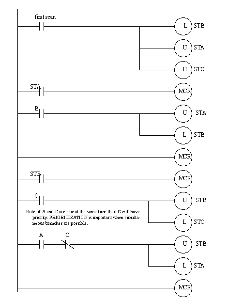
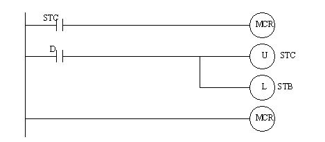
• Consider the state diagram below and implement it in ladder logic. You should anticipate what will happen if both A and C are pushed at the same time.
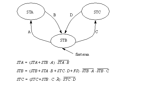
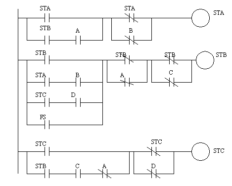
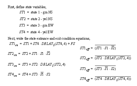
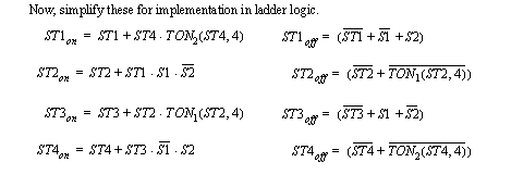
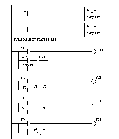
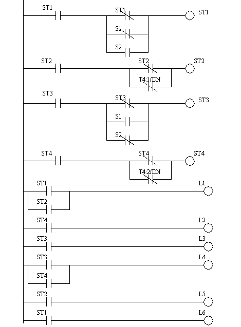
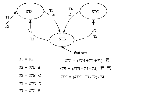
20.3.1.3 - Entry and Exit State Equations
• This method deals updates the logic in a single scan, and only has a problem with competing transitions.
• This implementation is based upon checking the state activation and deactivation separately.
• Consider the state diagram below and implement it in ladder logic. You should anticipate what will happen if both A and C are pushed at the same time.
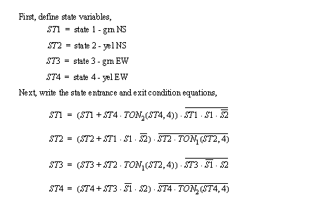
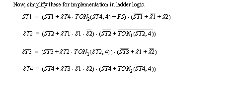
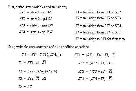
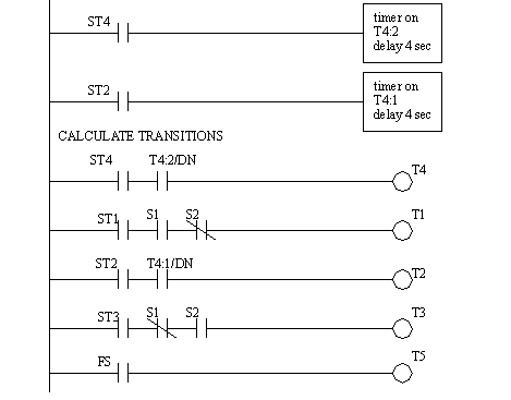
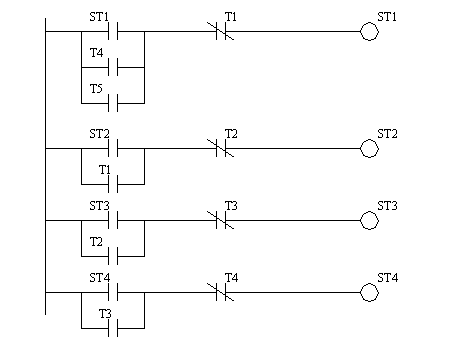
20.3.1.4 - State Transition Equations
• This method deals updates the logic in a single scan, and only has a problem with competing transitions.
• This implementation is based upon checking the state activation and deactivation separately.
• Consider the state diagram below and implement it in ladder logic. You should anticipate what will happen if both A and C are pushed at the same time.
Problem 20.6 Implement the previous state diagram in ladder logic.
20.4 Parallel Process Flowcharts
• Parallel Processes can happen separately but must eventually work together. This happens when PLC’s control multistage machines, etc.
• PLC’s are well suited to this problem.
• There is a method (based on Petri nets) that goes by a number of names,
GRAFCET: developed in France
IEC848: the standard developed from GRAFCET
SFC (Sequential Function Charts): Allen Bradley version
• The basic elements are,
flowlines: connects steps and transitions (these basically indicate sequence)
transition: causes a shift between steps, acts as a point of coordination
initial step: the first step
step: basically a state of operation. A state often has an associated action
macrostep: a collection of steps (basically a subroutine)
selection branch: an or: only one path is followed
simultaneous branch: an and: both (or more) paths are followed
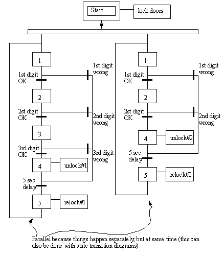
• The example below shows a SFQ for a a controller that is watching two separate doors. One door requires a two digit entry code, the second door requires a three digit entry code.
• SFC editors are available from many companies.
• SFCs can also be converted to ladder logic the same way state diagrams were.
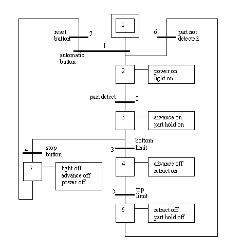
• Consider the example below,
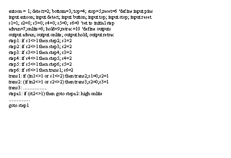
20.4.1 Implementation with Microcontroller
• We could also write a program for the basic stamp microcontroller,
Problem 20.7 Develop an SFC for a vending machine and expand it into ladder logic.
20.5 Sequential Logic Circuits
20.5.1 Latches and Seal-in
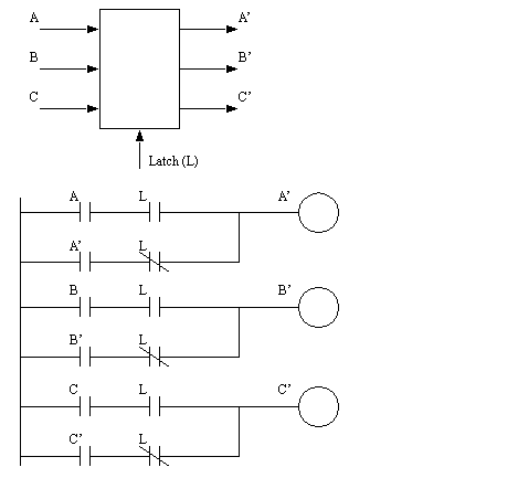
• Latches are one function built into PLCs, but there are variations.
• Basically, latches allow one or more values to be frozen in time.
• This circuit is a seal-in because the output locks the inputs on. After power is removed the logic will default to off.
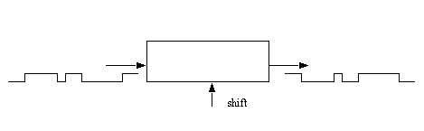
20.5.2 Shift Registers
• These allow values to be put into a ‘pipe-line’ where values are shifted through one at a time.
20.6 Problems
Problem 20.8 Design ladder logic for the following process description.
a) A toggle start switch (TS1) and a limit switch on a safety gate (LS1) must both be on before a solenoid (SOL1) can be energized to extend a stamping cylinder to the top of a part. Should a part detect sensor (PS1) also be considered? Explain your answer.
b) While the stamping solenoid is energized, it must remain energized until a limit switch (LS2) is activated. This second limit switch indicates the end of a stroke. At this point the solenoid should be de-energized, thus retracting the cylinder.
c) When the cylinder is fully retracted a limit switch (LS3) is activated. The cycle may not begin again until this limit switch is active. This is one way to ensure that a new part is present, is there another?
d) A cycle counter should also be included to allow counts of parts produced. When this value exceeds some variable amount (from 1 to 5000) the machine should shut down, and a job done light lit up.
e) A safety check should be included. If the cylinder solenoid has been on for more than 5 seconds, it suggests that the cylinder is jammed, or the machine has a fault. If this is the case the machine should be shut down, and a maintenance light turned on.
f) Implement the ladder diagram on a PLC in the laboratory.
g) Fully document the ladder logic and prepare a short report: This should be of use to another engineer that will be maintaining the system.
Problem 20.9 Write the ladder logic diagram that would be required to execute the following data manipulation for a preventative maintenance program.
i) Keep track of the number of times a motor was started with toggle switch #1.
ii) After 2000 motor starts turn on an indicator light on the operator panel.
iii) Provide the capability to change the number of motor starts being tracked, prior to triggering of the indicator light. HINT: This capability will only require the change of a value in a compare statement rather than the addition of new lines of logic.
iv) Keep track of the number of minutes that the motor has run.
v) After 9000 minutes of operation turn the motor off automatically and also turn on an indicator light on the operator panel.
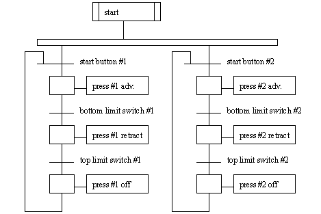
Problem 20.10 Develop an SFC for a two person assembly station. The station has two presses that may be used at the same time. Each press has a cycle button that will start the advance of the press. A bottom limit switch will stop the advance, and the cylinder must then be retracted until a top limit switch is hit.
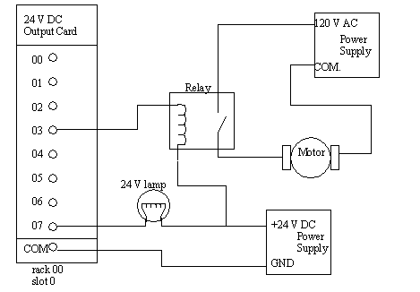
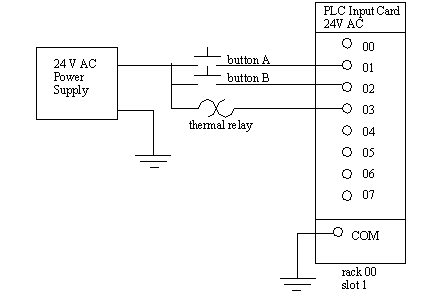
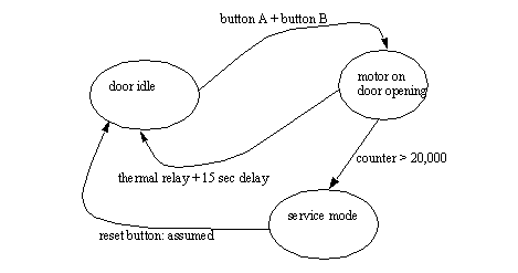
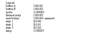
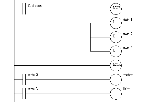
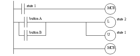
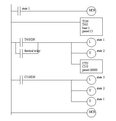
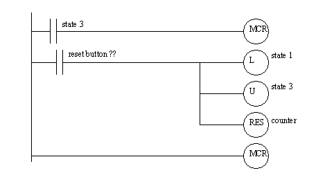
Problem 20.11 You have been asked to program a PLC-5 that is controlling a handicapped access door opener. The client has provided the electrical wiring diagram below to show how the PLC inputs and outputs have been wired. Button A is located inside and button B is located outside. When either button is pushed the motor will be turned on to open the door. The motor is to be kept on for a total of 15 seconds to allow the person to enter. After the motor is turned off the door will fall closed. In the event that somebody gets caught in the door the thermal relay will go off, and the motor should be turned off. After 20,000 cycles the door should stop working and the light should go on to indicate that maintenance is required.
a) Develop a state diagram for the control of the door.
b) Convert the state diagram to ladder logic. (list the input and the output addresses first)
c) Convert the state diagram to Boolean equations.
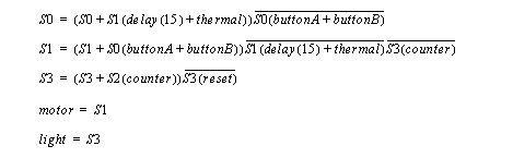
Answer 20.11
b)
c)
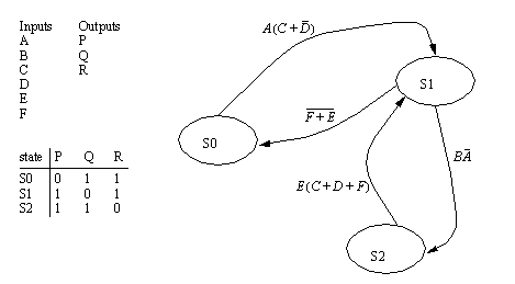
Problem 20.12 Convert the following state diagram to equations.
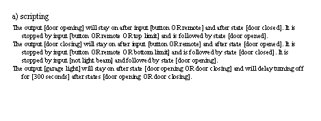
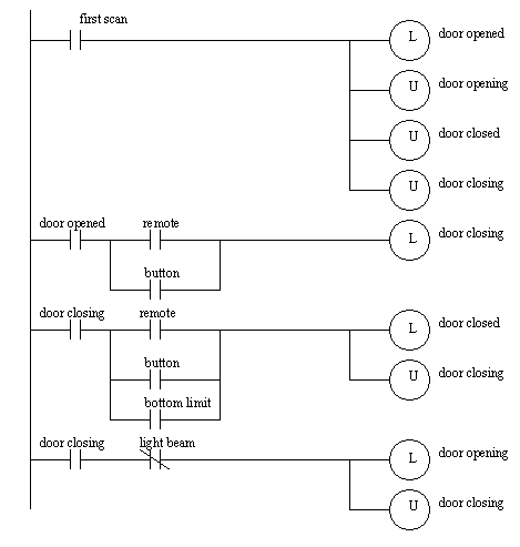
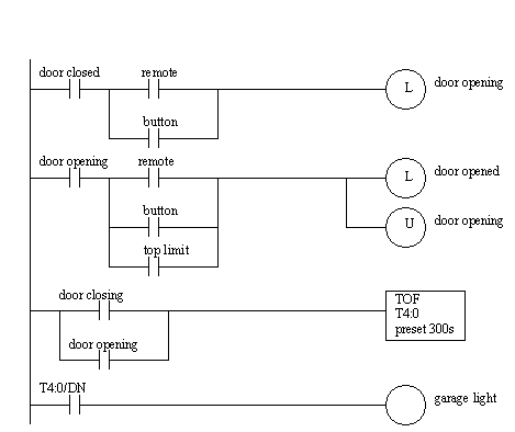
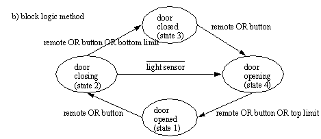
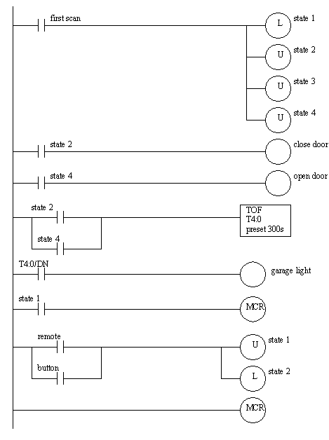
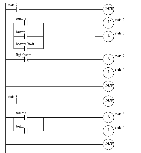
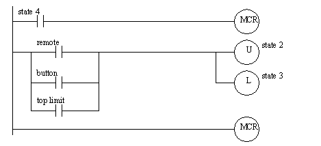
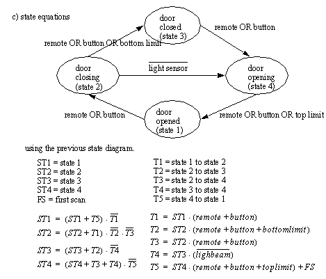
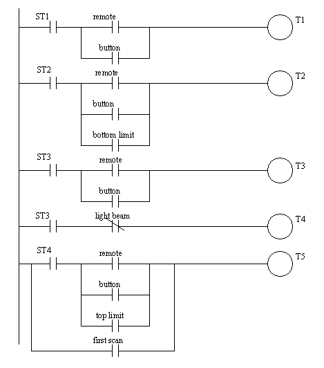
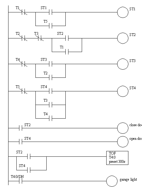
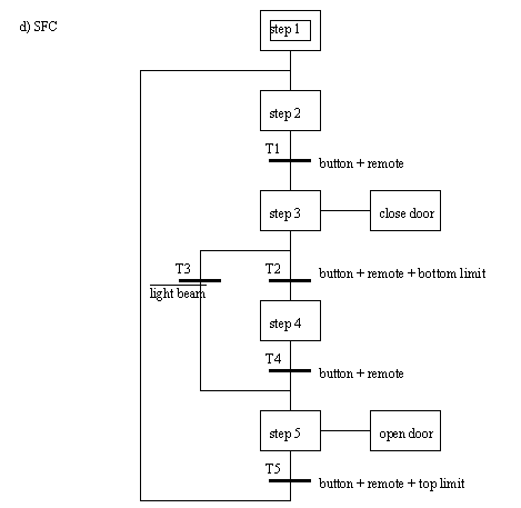
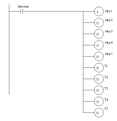
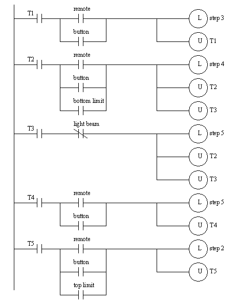
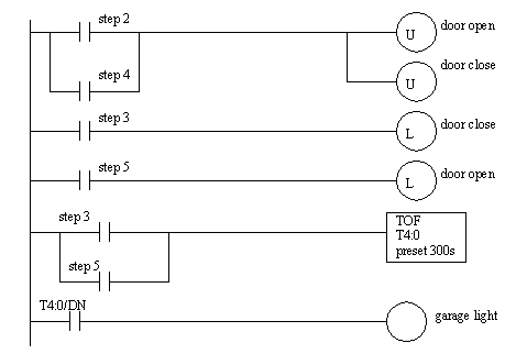
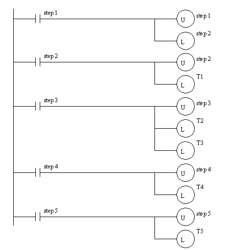
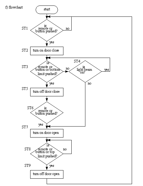
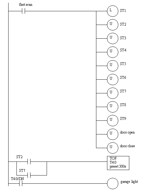
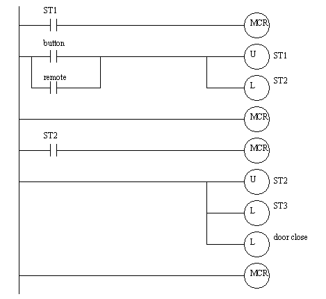
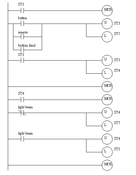
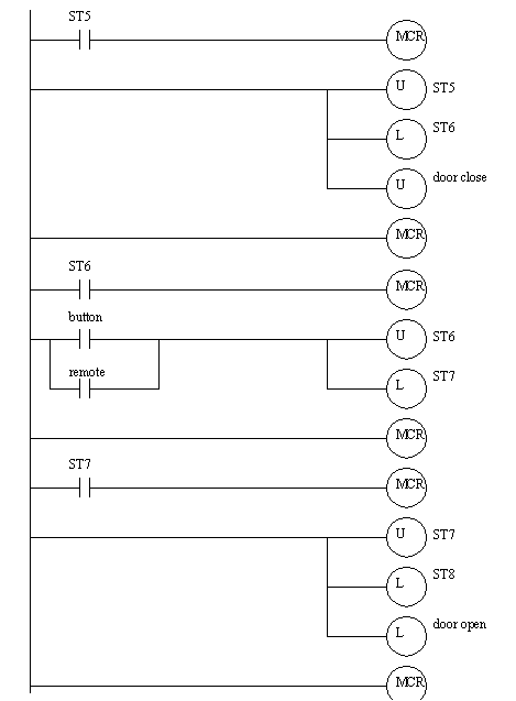
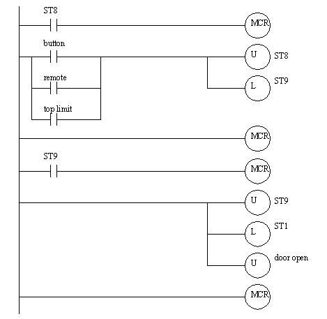
Problem 20.13 Design a garage door controller using four techniques a) scripts, b) block logic, c) state equations, d) SFCs and e) flowcharts. The behavior of the garage door controller is as follows,
- there is a single button in the garage, and a single button remote control.
- when the button is pushed the door will move up or down.
- if the button is pushed once while moving, the door will stop, a second push will start motion again in the opposite direction.
- there are top/bottom limit switches to stop the motion of the door.
- there is a light beam across the bottom of the door. If the beam is cut while the door is closing the door will stop and reverse.
- there is a garage light that will be on for 5 minutes after the door opens or closes.
Answer 20.13 a)
b)
c)
d)
f)
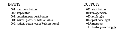
Problem 20.14 This morning you received a call from Mr. Ian M. Daasprate at the Old Fashioned Widget Company. In the past when they built a new machine they would used punched paper cards for control, but their supplier of punched paper readers went out of business in 1972 and they have decided to try using PLCs this time. He explains that the machine will dip wooden parts in varnish for 2 seconds, and then apply heat for 5 minutes to dry the coat, after this they are manually removed from the machine, and a new part is put in. They are also considering a premium line of parts that would call for a dip time of 30 seconds, and a drying time of 10 minutes. He then refers you to the project manager, Ann Nooyed.
You call Ann and she explains how the machine should operate. There should be start and stop buttons. The start button will be pressed when the new part has been loaded, and is ready to be coated. A light should be mounted to indicate when the machine is in operation. The part is mounted on a wheel that is rotated by a motor. To dip the part, the motor is turned on until a switch is closed. To remove the part from the dipping bath the motor is turned on until a second switch is closed. If the motor to rotate the wheel is on for more that 10 seconds before hitting a switch, the machine should be turned off, and a fault light turned on. The fault condition will be cleared by manually setting the machine back to its initial state, and hitting the start button twice. If the part has been dipped and dried properly, then a done light should be lit. To select a premium product you will use an input switch that needs to be pushed before the start button is pushed. She closes by saying she will be going on vacation and you need to have it done before she returns.
You hang up the phone and, after a bit of thought, decide to use a SLC-150 with the following outputs and inputs,
a) Draw a state diagram for the process.
b) List the relays needed to indicate when each state is on, and list any timers and counters used.
c) Write a Boolean expression for each transition in the state diagram.
d) Do a simple wiring diagram for the SLC-150.
e) Write the ladder logic for the state that involves moving the part into the dipping bath.
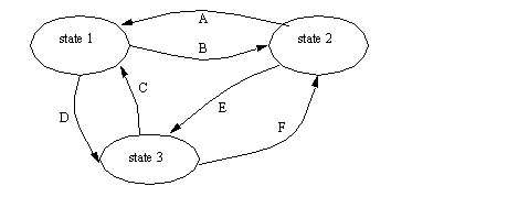
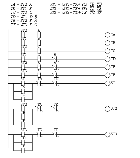
Problem 20.15 Given the following state diagram, use equations to implement ladder logic.
Answer 20.15
Problem 20.16 Convert the following flow chart to ladder logic.
Answer 20.16
Problem 20.17 Convert the following state diagram to logic using equations.
Answer 20.17
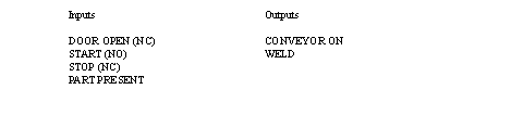
Problem 20.18 A welding station is controlled by a PLC. On the outside is a safety cage that must be closed while the cell is active. A belt moves the parts into the welding station and back out. An inductive proximity sensor detects when a part is in place for welding, and the belt is stopped. To weld, an actuator is turned on for 3 seconds. As normal the cell has start and stop push buttons.
a) Draw a flow chart
b) Implement the chart in ladder logic
Problem 20.19 In dangerous processes it is common to use two palm buttons that require a operator to use both hands to start a process (this keeps hands out of presses, etc.). To develop this there are two inputs (P1 and P2) that must both be turned on within 0.25s of each other before a machine cycle may begin.
Develop ladder logic to control a process that has a start (START) and stop (STOP) button for the power. After the power is on the palm buttons (P1 and P2) may be used as described above to start a cycle. The cycle will consist of turning on an output (MOVE) for 2 seconds. After the press has been cycled 1000 times the press power should turn off and an output (LIGHT) should go on.
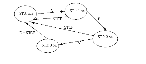
Problem 20.20 Convert the following state diagram to ladder logic using equations. Give the stop button higher priority.