• There are a number of defining properties of interest when considering sensors,
Accuracy: a sensor will statistically vary about an exact reading. If we take a statistical range for all readings (e.g., ±3 standard deviations) this will be a reasonable accuracy. Accuracy can also be given as a relative value (e.g. percentage)
Resolution: Typically used for systems that ‘step’ through readings. This is the smallest increment that the sensor can detect.
Repeatability: When a single sensor condition is made and repeated, there will be a small variation for that particular reading. This is the repeatability.
Range: Natural limits for the sensor
Dynamic Response: the frequency range for regular operation of the sensor. Typically sensors will have an upper operation frequency, occasionally there will be lower frequency limits.
Environmental: temperature and humidity limits exist for many sensors
Calibration: most sensors require some degree of calibration, and their readings may drift over time.
• Analog signals are more complicated to deal with than digital signals. This is primarily because electrical noise will degrade the quality of the signal quickly.
• To deal with this there are a number of measures to be taken,
shielding: shielding is used to reduce the effects of electromagnetic interference.
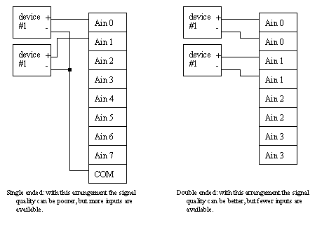
single/double ended inputs: shared or isolated reference voltages (commons).
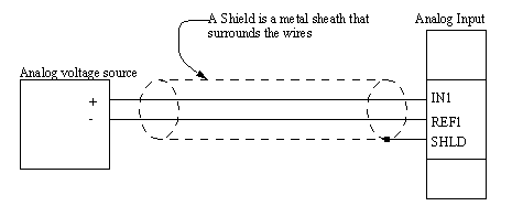
• A simple shielding example is shown below. A shielded cable has a metal sheath. This sheath needs to be connected to the measuring device to allow induced currents to be drained. This prevents electromagnetic waves to induce voltages in the signal wires.

• The common voltage for each analog signal may be the same but more often it is different. If the commons are tied together we have a single ended system. If each signal is given its own common the connections are double ended. Most analog input cards allow a choice between one or the other.
• Signals from transducers are normally small and cannot be directly input into an analog input. To make these signals more usable Signal Conditioners are used.
• Signal conditioners are normally amplifiers to increase the signal strength, but some will also change the signal (eg. conversion from current to voltage).
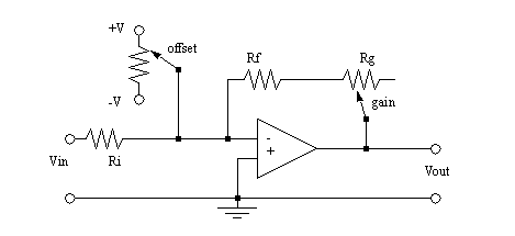
• An example of a simple single ended amplifier is given below,
• An example of a differential amplifier with a current input is given below. Note that Rc converts a current to a voltage.
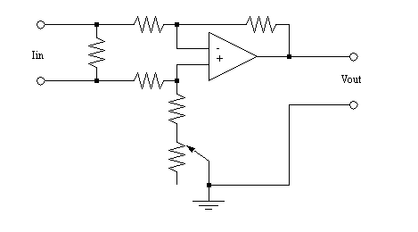
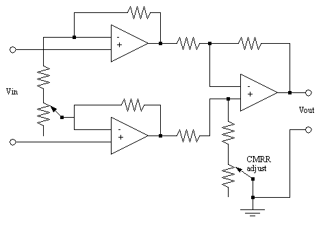
• An example of a differential to single ended amplifier is given below.
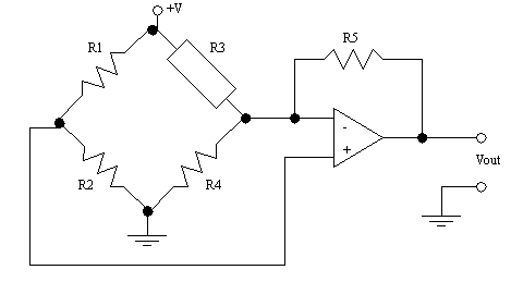
• The circuit below can be used to amplify the output of a resistive device.
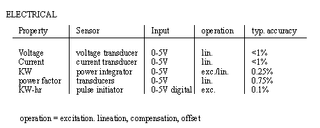
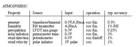
• A list of physical properties, and sensors to measure them is given below,



Ammeter: meter to indicate electrical current
Bourdon tube: widely used industrial gage to measure pressure and vacuum
Chromatographic instruments: laboratory-type instruments used to analyze chemical compounds and gases.
Inductance-coil pulse generator: transducer used to measure rotational speed. Output is pulse train.
Linear-Variable-Differential transformer (LVDT) electromechanical transducer used to measure angular or linear displacement. Output is Voltage
Manometer: liquid column gage used widely in industry to measure pressure.
Ohmmeter: meter to indicate electrical resistance
Optical Pyrometer: device to measure temperature of an object at high temperatures by sensing the brightness of an objects surface.
Orifice Plate: widely used flowmeter to indicate fluid flow rates
Photometric Transducers: a class of transducers used to sense light, including phototubes, photodiodes, phototransistors, and photoconductors.
Piezoelectric Accelerometer: Transducer used to measure vibration. Output is emf.
Pitot Tube: Laboratory device used to measure flow.
Positive displacement Flowmeter: Variety of transducers used to measure flow. Typical output is pulse train.
Potentiometer: instrument used to measure voltage
Pressure Transducers: A class of transducers used to measure pressure. Typical output is voltage. Operation of the transducer can be based on strain gages or other devices.
Radiation pyrometer: device to measure temperature by sensing the thermal radiation emitted from the object.
Strain Gage: Widely used to indicate torque, force, pressure, and other variables. Output is change in resistance due to strain, which can be converted into voltage.
Thermistor: Also called a resistance thermometer; an instrument used to measure temperature. Operation is based on change in resistance as a function of temperature.
Thermocouple: widely used temperature transducer based on the Seebeck effect, in which a junction of two dissimilar metals emits emf related to temperature.
Turbine Flowmeter: transducer to measure flow rate. Output is pulse train.
Venturi Tube: device used to measure flow rates.
• A variable resistor is used to convert an angle or displacement to resistance/voltage.
• These give absolute position readings.
• Linear resistors are used for measuring linear displacement.
• The basic principle of operation is that a moving wiper (sensor input) moves a contact along a resistor. The ends of the resistor are connected to reference voltages. As the wiper moves the potentiometer acts as a voltage divider and produces a voltage proportional to position.
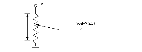
• rotational potentiometers are the most popular. These may be limited to a fixed range either less than 360, or some number of turns.
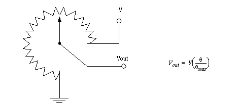
very common in a variety of forms, resistances, etc.
limited accuracy (there are high cost solutions)
• An incremental encoder will produce a set of output pulses, and a direction as it is rotated.
• The encoder contains an optical disk with fine windows etched into it. As the encoder shaft is rotated, the etched disk inside rotates. As it rotates various optical sensors are turned on and off.
absolute: the same shaft position will always give the same position reading
relative/incremental: these just indicate movement, and they require that other circuits or programs be used to track position
• How the openings are etched onto the disk determine whether it is absolute or relative.
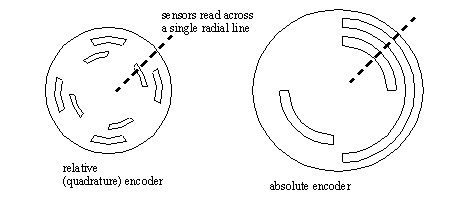
• In actual encoders there can be thousands of divisions per rotation.
• With an absolute encoder the output is a binary or gray code number.
• A quadrature pulse counter uses two pulses out of phase and deduces distance and direction.
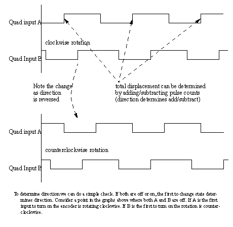
• These use small magnetic coils to detect positions and behave much like relative encoders.
Problem 11.1 What is the resolution of an absolute optical encoder that has six tracks? nine tracks? twelve tracks?
• A variable resistor is used to convert a displacement to resistance/voltage.
• These give absolute position readings.
• The basic principle of operation is that a moving wiper (sensor input) moves a contact along a resistor. The ends of the resistor are connected to reference voltages. As the wiper moves the potentiometer acts as a voltage divider and produces a voltage proportional to position.

• This is effectively a transformer with a moving inner core. The moving core changes the inductance, and this can be converted to a position.
• In these devices there are three sets of windings. The first set of windings is in the center, and is powered by an AC source. The other two coils are at the opposite sides of the main coils. As the core is moved forward/back the magnetic coupling will change.
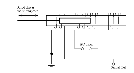
• If the core shown is in the center, the output will be 0Vac, as it shifts to the left there will be more coupling between the center and left coil, and the signal magnitude will be larger than the right hand coil. This difference can be converted to a calculated difference.
• This sensor is used for linear position sensing to high accuracies such as,
dimensional measurement for SPC
• The signals from the LVDT can be conditioned with the circuit below.
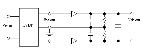
• Near the center of the movement range the voltage is linearly proportional to core movement.
• By overlapping two fine lines patterns we can measure displacement.
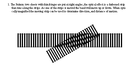
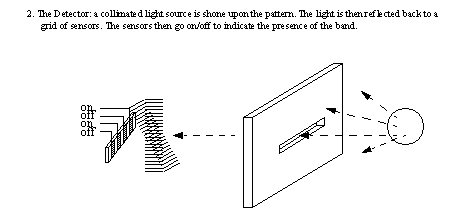
• These are used in high precision applications, and are not available as off the shelf sensors.
• Uses the fact that when light is 180 degrees out of phase it cancels out.
• By finding the phase between outgoing and returning light (from lasers typically) the distance can be found.
• This can be measured with dedicated sensors.
• We may also differential the output of a position sensor to find a velocity
• Output voltage is proportional to velocity (V/(cm/s))
• These devices have low natural frequencies, and are used for signals with higher frequencies.
• well suited to measuring severe vibrations, but it may be affected by noise from AC sources.
• because signals are velocity, some form of integration must be done, making these devices bulky, and somewhat inaccurate
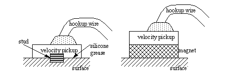
• There are two common methods for mounting velocity pickups,
Magnetic mounts allow fast and easy mounting, but the magnetic mount acts as a slight spring mass isolator, limiting the frequency range.
Stud mounted transducers have a thin layer of silicone grease to improve contact
• These devices measure the angular velocity of a rotating shaft.
• One way is to connect a DC generator (motor). The faster the shaft turns, the higher the voltage.
• Another technique uses a magnet with a pickup coil. As the magnet passes the coil a pulse is generated. The pulse magnitude and frequency are proportional to speed.
• Like velocity we may also find acceleration by differentiating velocity, or by differentiating position twice.
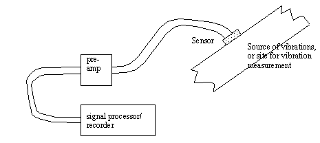
Vibration Source: hammers can be used to generate impulse/step function responses. Load cells/vibrators can be used to excite frequency responses (Bode plots and phase shift plots)
Sensors: Velocity Pickups/Accelerometers: lightweight devices that are mounted on structures. They produce small voltages (approx. 10mV). Velocity meters are not as accurate as accelerometers. Accelerometers are very common, and are used for vibrations above 1KHz. Many other sensors are possible.
Preamplifiers: Can power sensors, filter and amplify output.
Signal Processor: Many types used, from software packages, to older pen based plotters, or tape recorders
• Compared to velocity pickups
• electronic integrators can provide velocity and position
• The accelerometer is mounted with electrically isolated studs and washers, so that the sensor may be grounded at the amplifier to reduce electrical noise.

• Cables are fixed to the surface of the object close to the accelerometer, and are fixed to the surface as often as possible to prevent noise from the cable striking the surface.
• Background vibrations in factories are measured by attaching control electrodes to ‘non-vibrating’ surfaces. (The control vibrations should be less than 1/3 of the signal for the error to be less than 12%)
• Piezoelectric accelerometers typically have parameters such as,
operate well below one forth of the natural frequency
• Accelerometer designs vary, so the manufacturers specifications should be followed during application.
• There is often a trade-off between wide frequency range and device sensitivity (high sensitivity requires greater mass)
• Two type of accelerometers are compression and shear types.
• Mass of the accelerometers should be less than a tenth of the measurement mass.
• Accelerometers can be linear up to 50,000 to 100,000 m/s**2 or up to 1,000,000 m/s**2 for high shock designs.
• Typically used for 10-10,000 Hz, but can be used up to 10KHz
• Temperature variations can reduce the accuracy of the sensors.

• These devices can be calibrated with shakers, for example a 1g shaker will hit a peak velocity of 9.81 m/s**2
• These values cannot currently be measured directly, and count on indirect measurements based on deflections or strain.
• These devices are attached to surfaces. As the surfaces experience stress/strain the devices are stretched and the resistance changes.
• The basic theory is based on a stretched wire.
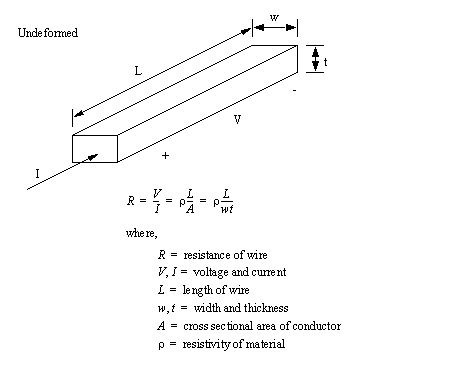
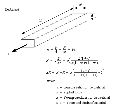
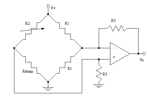
• Changes in strain gauge values are typically small (large values would require strains that would cause the gages to plastically deform). As a result the resistance values are also small, so we can use resistor bridges (eg whetstone bridge) to amplify the effect. In this circuit the variable resistor R2 should be turned until the circuit is balanced for no strain.
• If the strain gauge is placed in the direction of the strain it will read the full strain. If the gauge is perpendicular, the reading will be zero.
uniaxial: the direction is critical
rosette: two gages at 90deg. to each other will measure strain components in two direction (and can measure shear).

• In some machines (etc.) a strain gauge is often mounted on a narrowed member to measure force. This is typically known as a load cell.

• Strain gages are normally made on thin films that are attached (mounted) to surfaces through a process that involves surface preparation and attachment with adhesives.
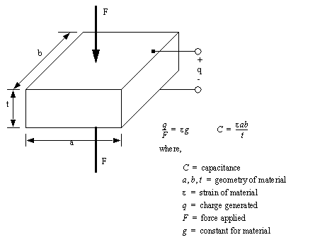
• These are ceramic and crystal materials that will generate a small amount of charge when deformed (the capacitance also changes).
• If the deformation is linear,
• Fluid flow rate is important for a number of processes such as cooling and chemical.
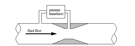
• A Venturi valve uses a narrow section of a pipe to generate a pressure differential from the normal pipe diameter. The pressure differential will increase with the velocity of the flow. By measuring the pressure we can determine the flow rate.
• Temperature is of significant concern in most disciplines.
fine temperature measurements 0-100 deg C: e.g. science/laboratory work
high temperature measurements <3000 deg F: e.g. metal refining/processing
low temperature measurement 0--60 deg C: e.g. freezers
very low temperatures <-60 deg C: e.g. superconductors in MRI units
very high temperatures > 2000 deg C: e.g. fusion research
• These devices use the effects of temperature change on conductivity.
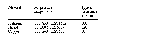
• Uses resistive wires made of materials such as,
• Typical material properties are, [Bryan]
• Wires are wound about an insulator, for support, and covered for protection.
• These devices typically have positive temperature coefficients that cause resistance to increase linearly with temperature.
• Typical changes are doubling of initial resistance value over range of use.
more linear than thermocouples
small absolute resistance and resistance change
• Uses a junction of dissimilar metals to generate a voltage proportional to temperature.
• The bimetalic junction will generate an electrical potential between the metals as the temperature increases. The change in voltage is linearly proportional to the change in temperature.
• When using a thermocouple for precision measurement, a second thermocouple can be kept at a known temperature for reference.
• A series of thermocouples connected together in series produces a higher voltage and is called a thermopile.
• Basic thermocouple types are J, K, etc. These are designed for different temperature ranges.
• The basic calculations for thermocouples are given below,

inexpensive and commonly available
• Non-linear devices that change conductivity with temperature. These are usually semiconductors.
• The resistance drops as the temperature rises. (Note: this is because the extra heat reduces electron mobility in the semiconductor.) This effect can change the resistance by more than 1000 times.
• The basic calculation for thermistors is given below,

• The circuit below can be used to amplify the output of these devices.
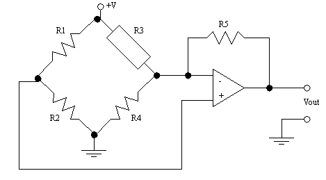
• These devices are normally small and come as beads or metalized surfaces.
• The advantages of these devices include,
higher resistance reduces the effect of lead impedance
• Convert sound pressure to electrical signals
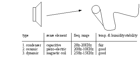
• A microphone has a finite area to measure the sound with. As the diameter ‘d’ approaches the wavelength of sound, the sound becomes distorted.

• When wind blows across a microphone, it generates a low frequency turbulence noise. This is often corrected by using dBA measurements, and foam balls.
• Corrections must also be made for changes in temperature and altitude

• These devices change from high resistance (>Mohms) in the dark to low resistance (<Kohms) in bright light.
• The change in resistance is non-linear, and occurs relatively slowly also.
• A simple comparator circuit is shown below.
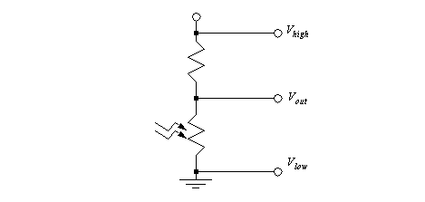
• This sensor is relatively easy to design with.
• Converts pressure to a linear translation. Basically a twisted section of flexible tube will try to straighten out as pressure is applied.
• One end of the tube is fixed, and the other end moves freely as pressure is applied. An LVDT can be used to measure the position.
Problem 11.2 Suggest a couple of methods for collecting data on the factory floor
Problem 11.3 If a thermocouple generates a voltage of 30mV at 800F and 40mV at 100F, what voltage will be generated at 1200F?
Problem 11.4 A certain potentiometer is to be used as the feedback device to indicate position of the output link of a rotational robot joint. The excitation voltage of the potentiometer equals 5.0 V, and the total wiper travel of the potentiometer is 300 degrees. The wiper arm is directly connected to the rotational joint so that a given rotation of the joint corresponds to an equal rotation of the wiper arm.
a) Determine the voltage constant of the potentiometer Kp,
b) The robot joint is actuated to a certain angle, causing the wiper position to be 38 degrees. Determine the resulting output voltage of the potentiometer.
c) In another actuation of the joint, the resulting output voltage of the potentiometer is 3.75V. Determine the corresponding angular position of the output link.
Problem 11.5 How is the efficiency of a motor defined?
Problem 11.6 What is the relationship between Real Power, Reactive Power and Apparent Power? (A sketch is acceptable)
Problem 11.7 What is the definition of the power factor of a motor?
Problem 11.8 Name two ways to improve motor efficiency.
Problem 11.9 Name two types of inputs that would be analog input values (versus a digital value).
Problem 11.10 Describe the following as either Transient or Steady State problems with respect to Power Quality:
Electrical Noise _________________________
Tingle Voltage _______________________
11.1 Bryan, L.A. and Bryan, E.A., Programmable Controllers; Theory and Implementation, Industrial Text Co., 1988.
11.2 Swainston, F., A Systems Approach to Programmable Controllers, Delmar Publishers Inc., 1992.