25. Linkage Analysis and Synthesis
• The large number of possible ways to satisfy design criteria make it hard for us to select a single useful mechanism.
• The design techniques outlined below can help narrow down, or select a specific mechanism.
• To do the design work we typically begin with some functional specifications for a path of motion. These specifications typically include one or more of the following,
rotational motions (i.e. shaft)
differing advance/return times
small stop/dwell times
straight line segments in path
specific velocities along path
a curved path
• Some points of interest about the selection of linkages in design,
linkages can be used in place of cams to,
reduce forces
eliminate loading spring
simplify manufacture and tolerance problems
the space required for these linkages may be larger than cams
in many cases ratios are specified. After we get these we will design the weakest member to be mechanically adequate, and then design the other parts.
25.1 Selection of Mechanism Types
• When trying to select a mechanism type one way is, (NOTE: there is no exact way to this, and you need to exercise some creativity)
1. Examine the motion profile required.
2. Determine the distinct phases of motion, and estimate the d.o.f. needs for each/all.
3. Look for crosses in path, dwell spots, motion reversal, straight line segments, etc.
4. Consider the various configurations you know of and how they satisfy parts or all of the motion. The DOF can be used to suggest the number of links and types of joints required (i.e. Grashof’s criteria).
5. If no satisfactory solutions are available, the look to a handbook of available mechanisms for other ideas.
6. Use design techniques for the specific mechanisms to determine dimensions
7. Test the design on Working Model, or by building a prototype.
• Shigley and Uicker identify three types of common linkage problems to look for,
Function generation: in this case we want to drive an output shaft (angular displacement) using an input shaft (angular displacement). This function can also be performed using cams with oscillating followers.
Prescribed Path Shape: Here we follow a point on the mechanism as it follows a path through space.
Body Guidance: A combination of translation and rotation may be used to move an object.
• Erdman and Sandor also introduce the idea of choosing mechanisms into stages,
1. Type synthesis
2. Dimensional synthesis
25.2 Design Methods: Synthesis
• This stage is somewhat inexact and should involve a few questions about the application.
Is there a starting/ending position?
What is the starting ending position?
Are there dimensional limits?
How much power must be transmitted?
Is the mechanism function generating, prescribed path or body guidance?
How fast is the mechanism?
Does the motion need to be smooth?
How many degrees of freedom does the motion require?
Is the input/output motion type known? (i.e. rotation, linear, other)
Are inertial effects desired?
Can the mechanisms be planar/3D?
How much error is permissible? Is accuracy needed at all points?
Does the mechanisms appear to have multiple modes of motion?
• There are a number of excellent books that can be used to find suitable matches. These can often be modified to suit your needs. This technique is often known as ‘cookbook’.
25.1 Chironis & Sclater, Mechanisms and Mechanical Devices Sourcebook, McGraw-Hill, 1995
25.2 Jones, F.D., Ingenious Mechanisms for designers and inventors, Industrial Press Inc., Volumes 1-4, 1930.
25.2.1 Mechanism Typing
• This method helps systematically generate mechanism types.
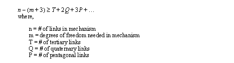
• We begin by considering the Gruebler/Kutzbach equation rewritten,
• After the # of degrees of freedom for the application are determined we can then use the equation to generate alternatives.
1. Examine # dof in the application.
2. Pick a # of links in the mechanism.
3. List values of B, T, Q, P, etc. that satisfy the equation.
4. Sketch mechanisms based on the list of B, T, Q, P, etc.
5. Sketch a suitable mechanism and then do detailed design.
6. If the design isn’t satisfactory choose a new mechanism.
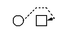
Problem 25.1 select a general mechanism to reach around a box and push on the back side and then retract.
25.3 Design Methods: Dimensional
• What follows is an assorted collection of independent design techniques.
• These techniques can be used after the general mechanism type has been selected.
• Learning these techniques before they are needed can help in the initial selection of mechanism types.
25.3.1 Two Position Design
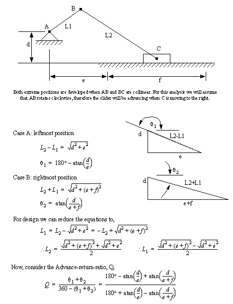
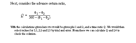
• When we have an advance-return-ratio we can use the basic geometry of a linkage to specify dimensions.
• For this approach we are given the extreme angular or position displacements.
• We can then calculate the geometry of the mechanisms at the two extreme two positions.
• If we are considering a slider crank mechanism we can find the extremes as shown below. A general relationship may be derived that can be used for subsequent design.
• The next stage in design is to select, or constrain some values, and then through trial and error estimate a design.
Problem 25.2 Assuming we have decided to use a crank slider mechanism with a slide of 30cm, and a advance-return-ratio of 1.2, what would the remaining dimensions be. (Hint: you will have to select values for ‘d’ and ‘e’, and check Q for a match, and L1 and L2 for reasonable sizes). Use mathcad, or a programmable calculator.
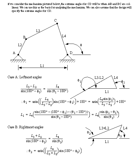
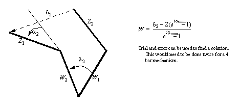
• A similar case arises when we are planning to design a crank-rocker mechanism for return time.
Problem 25.3 Design a four bar linkage that gives the following values,
• We can also use a closed form solution based on dyads.
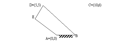
Problem 25.4 Design a 4 bar mechanism to reach the points C and D below,
• Consider the design problem below,
25.4 References
25.3 Erdman, A.G. and Sandor, G.N., Mechanism Design Analysis and Synthesis, Vol. 1, 3rd Edition, Prentice Hall, 1997.
25.4 Shigley, J.E., Uicker, J.J., Theory of Machines and Mechanisms, 2nd Edition, McGraw-Hill, 1995.